1. Introduction
Injection moulding is one of the most widely used manufacturing processes for producing plastic components. It is used in industries such as automotive, electronics, medical equipment, packaging, household products, toys, and consumer goods.
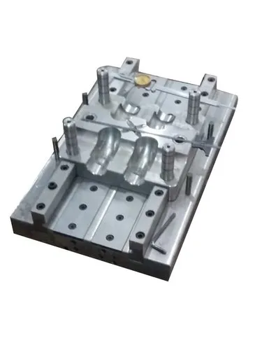
In injection moulding, plastic granules are heated inside a barrel until they melt. The molten plastic is then injected into a closed mould under pressure. After filling the mould, the plastic is cooled and solidified before the finished component is ejected.
Although injection moulding is a highly efficient manufacturing process, different defects can occur during production. These defects may affect the appearance, dimensions, strength, and functionality of the finished product.
Injection moulding defects can be caused by several factors, including:
- Incorrect processing parameters
- Poor mould design
- Improper mould maintenance
- Incorrect material selection
- Moisture in the plastic material
- Inadequate cooling
- Incorrect machine settings
- Improper venting
- Contamination of raw materials
Understanding common injection moulding defects is essential for maintaining product quality, reducing rejection rates, and improving production efficiency.
2. Short Shot
Common defect
Definition
A short shot occurs when molten plastic does not completely fill the mould cavity. As a result, the finished component is incomplete and some sections are missing.
Causes
- Insufficient injection pressure.
- Low injection speed.
- Insufficient material quantity.
- Low melt temperature.
- Low mould temperature.
- Blocked or restricted gates and runners.
- Poor mould venting.
- High material viscosity.
- Incorrect shot size.
Corrective Actions
- Increase injection pressure within the machine and mould limits.
- Increase injection speed where appropriate.
- Increase melt temperature if the material is too viscous.
- Check the mould temperature.
- Inspect the gate and runner system for restrictions.
- Clean blocked vents.
- Check the shot size and injection stroke.
- Verify that the correct material grade is being used.
Prevention
Maintain suitable injection parameters, clean the mould regularly, and ensure that the mould cavity fills completely during production.
3. Flash
Common defect
Definition
Flash is a thin layer of excess plastic that escapes from the mould cavity and solidifies along the mould parting line, ejector pins, or other gaps.
Causes
- Excessive injection pressure.
- Excessive holding pressure.
- High melt temperature.
- Insufficient mould clamping force.
- Damaged mould parting surfaces.
- Worn mould inserts.
- Incorrect mould alignment.
- Excessive material quantity.
- Dirt or foreign particles between mould surfaces.
Corrective Actions
- Reduce injection pressure where appropriate.
- Adjust holding pressure and holding time.
- Check the mould clamping force.
- Inspect the parting line for damage.
- Clean the mould contact surfaces.
- Check mould alignment.
- Repair or replace damaged inserts.
- Verify the correct shot size.
Prevention
Maintain proper mould alignment, ensure sufficient clamping force, and inspect the parting surfaces regularly.
4. Sink Marks
Definition
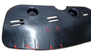
Sink marks are small depressions or indentations that appear on the surface of a moulded plastic component.
They commonly occur in thick sections, around ribs, bosses, and areas where the material takes longer to cool.
Causes
- Insufficient holding pressure.
- Insufficient holding time.
- Excessive wall thickness.
- Improper cooling.
- High melt temperature.
- Poor gate location.
- Uneven material shrinkage.
- Incorrect rib or boss design.
Corrective Actions
- Increase holding pressure within safe limits.
- Increase holding time until the gate freezes.
- Optimise cooling time.
- Reduce excessive wall thickness where possible.
- Improve rib and boss design.
- Adjust gate size and location.
- Optimise melt and mould temperatures.
Prevention
Use uniform wall thickness, suitable rib dimensions, and proper cooling system design.
5. Warpage
Definition
Warpage occurs when a moulded plastic component bends, twists, or changes shape after cooling.
The finished component does not maintain its intended dimensions or geometry.
Causes
- Uneven cooling.
- Uneven wall thickness.
- Improper mould temperature.
- Excessive or uneven packing pressure.
- Incorrect cooling time.
- High residual stresses.
- Poor gate location.
- Incorrect material selection.
- Improper ejection.
Corrective Actions
- Balance the mould cooling system.
- Adjust mould temperature.
- Optimise holding pressure and holding time.
- Increase cooling time if required.
- Improve wall thickness uniformity.
- Review gate position.
- Check the ejection system.
- Select a suitable material grade.
Prevention
Design the mould for balanced cooling and uniform material flow. Ensure that the component has sufficient time to cool before ejection.
6. Weld Lines (Knit Lines)
Definition
Weld lines are visible lines or weak areas formed when two or more separate streams of molten plastic meet inside the mould cavity but do not bond properly.
They commonly occur around holes, inserts, openings, and multiple flow paths.
Causes
- Low melt temperature.
- Low mould temperature.
- Low injection speed.
- Poor gate location.
- Poor venting.
- Material contamination.
- Excessive flow resistance.
- Inappropriate material selection.
Corrective Actions
- Increase melt temperature within the recommended range.
- Increase mould temperature where appropriate.
- Optimise injection speed.
- Improve mould venting.
- Modify gate location if necessary.
- Check the material for contamination.
- Review mould flow and cavity design.
Prevention
Design the gate and runner system to minimise weak meeting points and provide adequate venting.
7. Burn Marks
Definition
Burn marks are dark brown or black discolourations appearing on the surface of a plastic component.
They usually occur when trapped air or gases become excessively compressed and heated inside the mould cavity.
Causes
- Poor mould venting.
- Excessive injection speed.
- Excessive injection pressure.
- High melt temperature.
- Trapped air in the cavity.
- Material degradation.
- Blocked vents.
- Excessive screw speed or back pressure causing overheating.
Corrective Actions
- Clean the mould vents.
- Improve venting at the affected locations.
- Reduce injection speed where appropriate.
- Check melt temperature.
- Reduce excessive screw speed or back pressure.
- Check for material degradation.
- Inspect the barrel and screw for overheating or material deposits.
Prevention
Maintain clean vents, control melt temperature, and avoid excessive injection speed.
8. Silver Streaks (Splay Marks)
Definition
Silver streaks are shiny, silver-coloured lines or streaks appearing on the surface of moulded plastic components.
They are often caused by moisture, volatile substances, or gases in the molten plastic.
Causes
- Moisture in hygroscopic plastic materials.
- Improper drying temperature.
- Insufficient drying time.
- Excessive melt temperature.
- Excessive screw speed.
- Material contamination.
- Air trapped during plasticisation.
- Degradation of the material.
Corrective Actions
- Dry the material according to the manufacturer’s recommendations.
- Check the dryer temperature.
- Verify the drying time and airflow.
- Check the material storage conditions.
- Reduce excessive melt temperature.
- Adjust screw speed and back pressure.
- Use clean, uncontaminated material.
Prevention
Follow the correct drying procedure, especially for moisture-sensitive materials such as nylon, PET, polycarbonate, and ABS.
9. Black Spots
Definition
Black spots are small black or dark particles visible on the surface or inside the moulded plastic component.
They usually indicate material contamination or degradation.
Causes
- Burnt plastic deposits inside the barrel.
- Material degradation due to excessive heat.
- Contaminated raw material.
- Poor machine cleaning.
- Carbonised material deposits.
- Dead spots in the nozzle or hot runner.
- Contaminated regrind material.
- Improper material changeover.
Corrective Actions
- Purge the barrel and nozzle.
- Clean the screw and barrel when necessary.
- Inspect the hot runner system.
- Check raw material quality.
- Avoid excessive residence time.
- Follow the correct material changeover procedure.
- Inspect recycled material before use.
Prevention
Maintain machine cleanliness and avoid overheating or leaving material inside the barrel for excessive periods.
10. Flow Marks
Definition
Flow marks are visible lines, bands, or patterns on the surface of a moulded component.
They often follow the direction of molten plastic flow.
Causes
- Low melt temperature.
- Low mould temperature.
- Low injection speed.
- Improper gate design.
- Uneven material flow.
- Poor runner design.
- Excessive wall thickness variation.
- Improper injection pressure.
Corrective Actions
- Optimise injection speed.
- Adjust melt temperature.
- Adjust mould temperature.
- Review gate dimensions and location.
- Improve runner design.
- Check the material flow pattern.
- Maintain uniform wall thickness.
Prevention
Use suitable gate dimensions, balanced runners, and optimised processing parameters.
11. Vacuum Voids
Definition
Vacuum voids are empty spaces or cavities found inside a moulded plastic component.
They commonly occur in thick sections where the outer surface solidifies before the inner material has completely cooled and shrunk.
Causes
- Insufficient holding pressure.
- Insufficient holding time.
- Excessive wall thickness.
- Poor cooling.
- Incorrect gate size.
- Excessive material shrinkage.
- Improper packing conditions.
Corrective Actions
- Increase holding pressure within the recommended limits.
- Increase holding time.
- Improve gate design.
- Optimise cooling.
- Reduce excessive wall thickness.
- Adjust mould and melt temperatures.
Prevention
Design components with uniform wall thickness and ensure adequate packing before gate freeze-off.
12. Jetting
Definition
Jetting is a defect in which molten plastic enters the mould cavity as a narrow stream rather than flowing smoothly along the cavity wall.
It creates a snake-like or worm-shaped pattern on the component surface.
Causes
- Excessive injection speed.
- Poor gate location.
- Small gate dimensions.
- Low melt temperature.
- Incorrect flow direction.
- High material viscosity.
- Poor mould design.
Corrective Actions
- Reduce the initial injection speed.
- Use a controlled multi-stage injection profile.
- Modify gate location if necessary.
- Review gate dimensions.
- Increase melt temperature within the material limits.
- Improve the flow path.
Prevention
Ensure that molten plastic enters the cavity smoothly and does not form an uncontrolled free jet.
13. Ejector Pin Marks
Definition
Ejector pin marks are visible marks, dents, or raised areas appearing on the component surface where ejector pins push the component out of the mould.
Causes
- Insufficient cooling time.
- Excessive ejection force.
- Incorrect ejector pin position.
- Uneven ejection force.
- Poor mould surface finish.
- Incorrect draft angle.
- Component sticking inside the mould.
- Insufficient mould release properties.
Corrective Actions
- Increase cooling time.
- Check ejector pin alignment.
- Balance the ejection system.
- Reduce excessive ejection force.
- Improve the draft angle.
- Polish or repair the mould surface.
- Inspect ejector pins for wear or damage.
Prevention
Use properly designed ejector systems and ensure that components are sufficiently cooled before ejection.
14. Delamination
Definition
Delamination occurs when thin layers of material separate from the surface of a moulded component.
It may appear as peeling, flaking, or a layered surface.
Causes
- Incompatible materials mixed together.
- Material contamination.
- Incorrect material drying.
- Excessive moisture.
- Improper processing temperature.
- Poor bonding between material layers.
- Incorrect use of recycled material.
Corrective Actions
- Check the material grade.
- Avoid mixing incompatible polymers.
- Dry the material according to specifications.
- Check processing temperatures.
- Inspect recycled material quality.
- Improve material handling and storage.
Prevention
Use compatible raw materials and maintain strict material handling procedures.
15. Bubbles
Definition
Bubbles are gas-filled areas that appear on or inside a moulded plastic component.
They can affect the appearance and mechanical properties of the finished product.
Causes
- Moisture in the raw material.
- Trapped air inside the mould.
- Material degradation.
- Excessive melt temperature.
- Improper venting.
- Volatile substances in the material.
- Incorrect processing conditions.
Corrective Actions
- Dry the material properly.
- Check the mould venting.
- Reduce excessive melt temperature.
- Inspect material quality.
- Adjust injection speed and pressure.
- Check the machine for material overheating.
Prevention
Maintain proper material drying, mould venting, and temperature control.
16. Colour Variation
Definition
Colour variation occurs when the moulded components show inconsistent colour compared with the approved product specification.
It may appear as lighter areas, darker areas, uneven shades, or colour streaks.
Causes
- Poor masterbatch mixing.
- Incorrect masterbatch dosage.
- Inconsistent raw material.
- Material contamination.
- Excessive processing temperature.
- Improper mixing conditions.
- Different material residence times.
- Incorrect colourant selection.
Corrective Actions
- Check the masterbatch dosage.
- Verify the material mixing procedure.
- Clean the hopper and barrel.
- Use consistent raw materials.
- Check processing temperatures.
- Inspect the dosing equipment.
- Ensure that the colourant is compatible with the base polymer.
Prevention
Use accurate dosing equipment, approved masterbatch, and controlled mixing procedures.
17. Dimensional Variation
Definition
Dimensional variation occurs when the finished component does not meet the specified dimensions or tolerances.
The component may be oversized, undersized, or inconsistent between production cycles.
Causes
- Incorrect mould dimensions.
- Improper cooling time.
- Uneven shrinkage.
- Incorrect holding pressure.
- Fluctuating melt temperature.
- Unstable mould temperature.
- Excessive machine parameter variation.
- Mould wear or damage.
Corrective Actions
- Verify machine settings.
- Check mould temperature.
- Adjust holding pressure and time.
- Confirm cooling conditions.
- Inspect mould dimensions.
- Check for wear in mould inserts.
- Measure samples using calibrated instruments.
Prevention
Maintain stable process conditions and perform regular dimensional inspections.
18. Delayed Ejection and Sticking
Definition
This defect occurs when a moulded component sticks inside the mould and cannot be removed easily during the normal ejection cycle.
It can cause damage to the component and interrupt production.
Causes
- Insufficient draft angle.
- Rough mould surface.
- Excessive shrinkage around the core.
- Insufficient cooling.
- Incorrect ejector pin arrangement.
- Damaged mould surfaces.
- Improper mould release conditions.
Corrective Actions
- Check the draft angle.
- Polish the mould surface where required.
- Inspect ejector pins.
- Increase cooling time if necessary.
- Check the mould for damage.
- Review the component design.
- Confirm the correct ejection sequence.
Prevention
Ensure proper mould design, adequate draft angles, good surface finishing, and a balanced ejection system.
19. Summary of Common Injection Moulding Defects
| No. | Defect | Main cause | Typical corrective action |
|---|---|---|---|
| 1 | Short shot | Insufficient filling | Optimise injection pressure and speed |
| 2 | Flash | Excessive pressure or mould gap | Check clamping force and mould condition |
| 3 | Sink marks | Insufficient packing | Optimise holding pressure and time |
| 4 | Warpage | Uneven cooling | Balance cooling conditions |
| 5 | Weld lines | Poor bonding of flow fronts | Improve temperature and venting |
| 6 | Burn marks | Trapped air and overheating | Clean and improve mould vents |
| 7 | Silver streaks | Moisture or volatiles | Dry material correctly |
| 8 | Black spots | Contamination or degradation | Purge and clean the machine |
| 9 | Flow marks | Uneven material flow | Optimise injection and mould conditions |
| 10 | Vacuum voids | Internal shrinkage | Improve packing and cooling |
| 11 | Jetting | Uncontrolled melt entry | Adjust initial injection speed |
| 12 | Ejector pin marks | Excessive ejection force | Balance the ejection system |
| 13 | Delamination | Material incompatibility | Use compatible materials |
| 14 | Bubbles | Trapped gas or moisture | Improve drying and venting |
| 15 | Colour variation | Poor mixing | Control masterbatch dosing |
| 16 | Dimensional variation | Unstable process conditions | Control temperature and pressure |
| 17 | Sticking | Poor ejection conditions | Improve draft and mould finish |
20. Important Factors Affecting Injection Moulding Quality
To reduce defects, manufacturers must control several important production factors.
20.1 Material Temperature
The plastic must be heated to the correct processing temperature.
- Low temperature can cause poor flow and short shots.
- Excessive temperature can cause material degradation and burn marks.
20.2 Injection Pressure
Injection pressure must be sufficient to fill the mould cavity.
- Low pressure can cause incomplete filling.
- Excessive pressure can contribute to flash and mould stress.
20.3 Injection Speed
Injection speed controls how quickly molten plastic enters the mould.
- Low speed can cause premature cooling and flow problems.
- Excessive speed can cause jetting, trapped-air problems, and burn marks.
20.4 Holding Pressure
Holding pressure compensates for material shrinkage while the plastic cools.
- Insufficient holding pressure can cause sink marks and voids.
- Excessive holding pressure can create residual stress and flash.
20.5 Cooling Time
Cooling time allows the plastic to solidify sufficiently before ejection.
- Insufficient cooling can cause deformation and sticking.
- Excessive cooling can reduce production efficiency.
20.6 Mould Temperature
Mould temperature influences material flow, surface appearance, cooling, and shrinkage.
The correct temperature depends on the polymer being processed and the product design.
20.7 Venting
Venting allows trapped air and gases to escape from the mould cavity.
Poor venting can result in burn marks, short shots, and other surface defects.
21. Quality Control Methods for Injection Moulded Components
Quality control is necessary to identify defects before products are delivered to customers.
Common inspection methods include:
1. Visual inspection
Used to identify flash, sink marks, scratches, burn marks, bubbles, and colour variation.
2. Dimensional inspection
Used to check length, width, height, diameter, thickness, and other specified dimensions.
3. Weight inspection
Used to identify variations in shot weight and detect possible filling or packing problems.
4. Functional testing
Used to verify that the component performs its intended function.
5. Mechanical testing
Used to evaluate strength, impact resistance, flexibility, and other mechanical properties when required.
6. Process monitoring
Used to monitor injection pressure, melt temperature, mould temperature, cycle time, and other important machine parameters.
22. Preventive Maintenance to Reduce Moulding Defects
Regular preventive maintenance helps reduce machine breakdowns and product rejection.
Important maintenance activities include:
- Clean the mould cavity and core regularly.
- Inspect the parting line for damage.
- Check ejector pins and return pins.
- Inspect the cooling channels.
- Clean the hopper and material feeding system.
- Inspect the screw and barrel.
- Check the nozzle for blockage.
- Inspect hydraulic and clamping systems.
- Check temperature controllers.
- Maintain proper mould lubrication.
- Record maintenance activities.
23. Safety Precautions During Injection Moulding
Injection moulding machines operate under high temperature, pressure, and mechanical force. Therefore, operators and maintenance personnel must follow safety procedures.
Important precautions include:
- Wear appropriate personal protective equipment.
- Never touch molten plastic or hot machine surfaces.
- Do not open safety guards while the machine is operating.
- Follow lockout/tagout procedures during maintenance.
- Never place hands inside the mould area during automatic operation.
- Use suitable tools to remove stuck components.
- Follow the manufacturer’s operating instructions.
- Maintain good housekeeping around the machine.
- Ensure that emergency stops and safety interlocks work correctly.
- Allow hot components to cool before handling them where appropriate.
24. Conclusion
Injection moulding defects can affect the appearance, dimensions, strength, and functionality of plastic products. Common defects include short shots, flash, sink marks, warpage, weld lines, burn marks, silver streaks, black spots, flow marks, voids, jetting, and dimensional variation.
Most defects are related to incorrect processing conditions, material problems, mould design, inadequate maintenance, or poor machine operation.
To reduce defects, manufacturers must maintain proper control over material quality, injection pressure, injection speed, melt temperature, mould temperature, holding pressure, cooling time, and mould condition.
The key to successful injection moulding is to identify the root cause of each defect, apply the correct corrective action, and maintain stable production conditions.