1. Introduction to Compression Moulding Defects
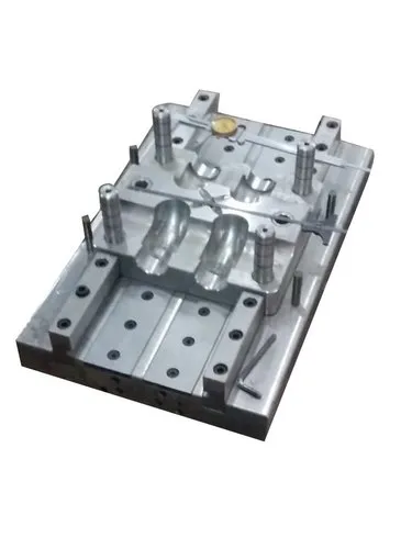
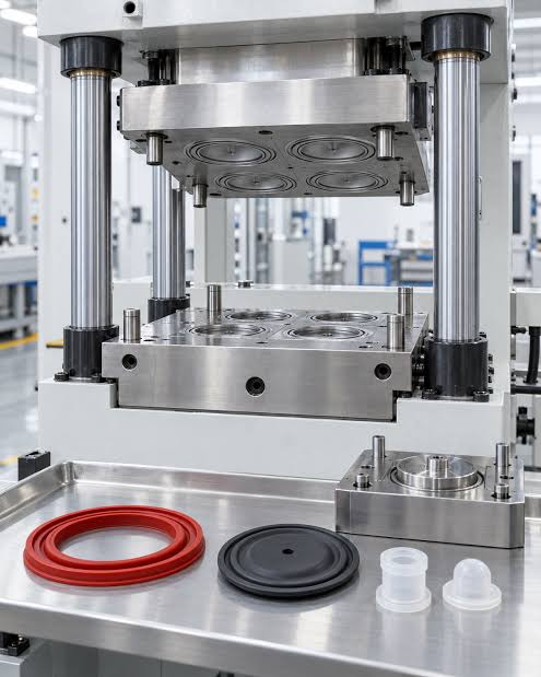
Compression moulding is a manufacturing process in which a measured quantity of material is placed into a heated mould cavity. The mould closes and applies pressure, forcing the material to flow and take the shape of the cavity. Heat and pressure help the material cure or solidify before the finished component is removed.
This process is widely used to manufacture plastic components, rubber products, electrical insulation parts, automotive components, and industrial products.
Although compression moulding is relatively straightforward, several defects can occur during production. These defects may affect the product’s appearance, dimensions, strength, surface quality, and overall performance.
Common causes include incorrect mould temperature, insufficient or excessive pressure, poor material preparation, improper charge quantity, inadequate venting, and incorrect curing time.
Understanding these defects helps manufacturers improve product quality, reduce material waste, and achieve consistent production.
2. Flash Formation
Flash formation is one of the most common defects in compression moulding. It occurs when excess material escapes through the gap between the mould halves.
Causes
- Excessive material placed in the mould cavity.
- Insufficient mould clamping pressure.
- Worn or damaged mould parting surfaces.
- Incorrect mould alignment.
- Excessive material flow during compression.
- Improper mould design.
Solutions
- Use the correct quantity of moulding material.
- Check that the mould closes completely.
- Inspect the parting surfaces for wear or damage.
- Maintain proper mould alignment.
- Adjust the moulding pressure according to the material requirements.
- Repair or replace damaged mould components when necessary.
Prevention tip: Accurate material measurement and regular inspection of the mould parting line help reduce flash formation.
3. Incomplete Filling
Incomplete filling occurs when the material fails to fill the entire mould cavity. As a result, the finished component may have missing sections, incomplete edges, or unformed details.
Causes
- Insufficient moulding material.
- Low mould temperature.
- Insufficient pressure.
- Poor material flow.
- Premature curing before the cavity is completely filled.
- Poor charge placement.
- Inadequate mould design or restricted material flow paths.
Solutions
- Measure the material charge accurately.
- Optimise mould temperature and pressure.
- Position the material correctly inside the cavity.
- Select a material with suitable flow characteristics.
- Review the mould design for restricted flow paths.
- Adjust the curing cycle to allow sufficient filling before the material sets.
Prevention tip: Correct charge placement and suitable temperature and pressure settings are essential for complete cavity filling.
4. Air Traps and Air Bubbles
Air traps occur when air becomes trapped inside the mould cavity or within the moulding material. These trapped gases may create bubbles, voids, or surface imperfections in the finished product.
Causes
- Inadequate mould venting.
- Air trapped during material loading.
- Moisture or volatile substances in the material.
- Improper charge placement.
- Rapid mould closure that prevents air from escaping.
- Contamination or unsuitable material preparation.
Solutions
- Improve the mould venting system.
- Ensure that the material is prepared and stored correctly.
- Position the material to allow air to escape during compression.
- Use a suitable mould-closing sequence.
- Apply controlled breathing or staged mould closure where appropriate for the material and process.
- Follow the material supplier’s recommendations for drying or preheating.
Prevention tip: Proper venting and material preparation help minimise internal voids and surface bubbles.
5. Sink Marks
Sink marks are shallow depressions or uneven areas that appear on the surface of a moulded component. They commonly occur when thicker sections cool or shrink differently from thinner sections.
Causes
- Uneven wall thickness.
- Excessively thick sections.
- Insufficient pressure during the required stage of moulding.
- Uneven heating or cooling.
- Incorrect material formulation.
- Inappropriate curing or cooling conditions.
Solutions
- Maintain reasonably uniform wall thickness.
- Reduce unnecessary thick sections through improved product design.
- Optimise mould temperature and pressure.
- Improve temperature distribution across the mould.
- Follow the material manufacturer’s recommended processing conditions.
Prevention tip: Good component design and consistent temperature control help reduce sink marks.
6. Warpage and Distortion
Warpage occurs when a moulded component bends, twists, or changes shape after moulding. The finished product may no longer match the required dimensions.
Causes
- Uneven mould temperature.
- Uneven cooling.
- Non-uniform material shrinkage.
- Incorrect curing time.
- Uneven pressure distribution.
- Premature removal from the mould.
- Poor component design.
Solutions
- Maintain uniform mould temperature.
- Improve the distribution of heat throughout the mould.
- Optimise curing and cooling times.
- Ensure even pressure distribution.
- Allow the component to cool or stabilise as required before handling.
- Review the component design to minimise uneven shrinkage.
Prevention tip: Balanced heating, appropriate curing, and controlled cooling are important for maintaining dimensional accuracy.
7. Surface Cracks
Surface cracks are visible fractures or fine lines that develop on the moulded component. Depending on their depth and location, they may reduce the product’s strength or cause it to fail during use.
Causes
- Excessive moulding pressure.
- Incorrect mould temperature.
- Improper curing.
- Material degradation.
- High internal stresses.
- Sharp corners or abrupt changes in component thickness.
- Damage during ejection or handling.
Solutions
- Optimise pressure and temperature settings.
- Follow the recommended curing cycle.
- Avoid overheating or prolonged exposure to excessive temperatures.
- Improve component design by reducing sharp transitions where practical.
- Use suitable ejection methods.
- Inspect the material for contamination or degradation.
Prevention tip: Correct processing conditions and smooth transitions in component geometry can help reduce cracking.
8. Burn Marks
Burn marks are dark, discoloured areas on the surface of a moulded component. They may result from excessive heat, degraded material, or compressed gases that become very hot during moulding.
Causes
- Excessive mould temperature.
- Excessively long heating or curing time.
- Poor venting.
- Trapped air or gases.
- Material degradation.
- Incorrect processing conditions.
Solutions
- Adjust the mould temperature according to the material specifications.
- Review the heating and curing cycle.
- Improve venting in areas where gases become trapped.
- Prevent excessive heating of the material.
- Check the mould for blocked vents or accumulated residue.
- Follow the material supplier’s processing recommendations.
Prevention tip: Proper temperature control and effective gas removal help prevent burn marks.
9. Short Shots
A short shot occurs when the material does not completely occupy the mould cavity, leaving part of the product unformed.
Although short shots and incomplete filling are closely related, the term short shot is commonly used to describe the resulting underfilled component.
Causes
- Insufficient material charge.
- Low pressure.
- Incorrect mould temperature.
- Poor material flow.
- Premature curing.
- Incorrect charge positioning.
Solutions
- Verify the quantity of material used for each moulding cycle.
- Adjust pressure within the recommended operating range.
- Maintain the appropriate mould temperature.
- Improve charge placement.
- Check whether the material has suitable flow characteristics.
- Review the mould design and curing sequence.
Prevention tip: Consistent charge weights and stable process settings help reduce short shots.
10. Delamination
Delamination occurs when layers or sections of a moulded component separate from one another. It may appear as peeling, splitting, or weak bonding between material layers.
This defect is particularly relevant to laminated materials, reinforced composites, and certain rubber or thermoset formulations.
Causes
- Contamination between material layers.
- Poor bonding between reinforcing layers.
- Incorrect curing conditions.
- Inadequate pressure.
- Moisture or trapped air.
- Incompatible material layers.
Solutions
- Clean materials and mould surfaces properly.
- Ensure that reinforcing layers are correctly positioned.
- Follow the specified curing temperature and time.
- Apply suitable pressure throughout the required moulding cycle.
- Use compatible materials and bonding systems.
- Improve venting where trapped air is contributing to separation.
Prevention tip: Clean materials, compatible layers, and controlled curing conditions are essential for good bonding.
11. Porosity and Internal Voids
Porosity refers to small pores or cavities within a moulded component. Internal voids may not be visible on the outside but can weaken the product or affect its sealing and electrical properties.
Causes
- Trapped air or gases.
- Moisture in the material.
- Volatile substances released during heating.
- Inadequate venting.
- Incorrect material preparation.
- Improper pressure or curing conditions.
Solutions
- Prepare and store the material according to supplier instructions.
- Improve mould venting.
- Use appropriate preheating or drying procedures where recommended.
- Optimise pressure and curing conditions.
- Inspect components using suitable testing methods when internal quality is critical.
Prevention tip: Internal voids can be difficult to detect visually, so inspection methods should match the product’s quality requirements.
12. Uneven Surface Finish
An uneven surface finish may include rough patches, dull areas, unwanted marks, or inconsistent texture across the component.
Causes
- Damaged or dirty mould surfaces.
- Uneven temperature distribution.
- Poor material flow.
- Incorrect pressure.
- Material contamination.
- Inadequate mould polishing or finishing.
- Material sticking to the mould.
Solutions
- Clean the mould cavity regularly.
- Inspect and repair damaged mould surfaces.
- Maintain consistent mould temperature.
- Optimise material placement and pressure.
- Prevent contamination during material preparation.
- Use a suitable mould release agent when required and approved for the material.
Prevention tip: Clean mould surfaces and consistent processing conditions help produce uniform finishes.
13. Material Sticking to the Mould
Material sticking occurs when the finished component does not release easily from the mould. It may become damaged during removal or leave residue inside the cavity.
Causes
- Insufficient draft or unsuitable mould geometry.
- Rough or damaged mould surfaces.
- Incorrect curing conditions.
- Inappropriate mould release agent.
- Material degradation or residue buildup.
- Excessive adhesion between the material and mould surface.
Solutions
- Inspect and clean the mould cavity.
- Improve the mould surface finish where necessary.
- Review the component’s release geometry.
- Use an appropriate release agent if permitted for the application.
- Adjust curing conditions according to the material specifications.
- Avoid excessive use of release agents, which may cause surface defects or interfere with bonding.
Prevention tip: Good mould design, proper surface maintenance, and a suitable release procedure reduce ejection problems.
14. Dimensional Inaccuracy
Dimensional inaccuracy occurs when a finished component does not meet the specified measurements, tolerances, or shape requirements.
Causes
- Incorrect mould dimensions.
- Uneven shrinkage.
- Poor temperature control.
- Inconsistent material quantities.
- Improper pressure.
- Mould wear or damage.
- Incorrect curing or cooling time.
Solutions
- Verify mould dimensions during tool inspection.
- Maintain stable processing conditions.
- Account for material shrinkage during mould design.
- Use consistent charge weights.
- Inspect critical dimensions at regular intervals.
- Repair worn mould components when required.
Prevention tip: Accurate tooling, controlled processing, and regular dimensional inspection are essential for producing consistent components.
15. Excessive Shrinkage
Shrinkage is the reduction in a component’s dimensions as the material cools or cures. Some shrinkage is normal, but excessive or inconsistent shrinkage can cause dimensional problems.
Causes
- Incorrect mould design allowances.
- Non-uniform temperature distribution.
- Improper curing or cooling.
- Incorrect material formulation.
- Variations in material charge.
- Processing conditions outside the recommended range.
Solutions
- Account for the expected shrinkage of the material during mould design.
- Maintain consistent mould temperature.
- Follow the recommended curing and cooling cycle.
- Use material from a controlled and suitable source.
- Monitor dimensions and adjust the process based on measured results.
Prevention tip: Material-specific shrinkage data should be considered during mould design and validated through production trials.
16. Colour Variation and Discolouration
Colour variation occurs when the finished components show inconsistent shades, streaks, spots, or unwanted discolouration.
This defect is particularly important in products where visual appearance is a major quality requirement.
Causes
- Uneven mixing of pigments or colourants.
- Incorrect material proportions.
- Excessive heating.
- Contamination.
- Inconsistent material batches.
- Residue on the mould surface.
Solutions
- Mix colourants uniformly according to the material supplier’s recommendations.
- Measure ingredients accurately.
- Maintain appropriate temperature and curing time.
- Prevent contamination during handling.
- Clean the mould regularly.
- Check incoming material batches for consistency.
Prevention tip: Accurate formulation and consistent material preparation help maintain uniform colour.
17. Incomplete Curing
Incomplete curing occurs when a thermosetting material or rubber compound has not completed the required curing reaction. The component may remain soft, weak, tacky, or dimensionally unstable.
This defect is especially important when compression moulding thermosets and rubber.
Causes
- Insufficient curing time.
- Low mould temperature.
- Incorrect material formulation.
- Uneven temperature distribution.
- Incorrect material quantity or placement.
- Processing conditions that do not match the material requirements.
Solutions
- Follow the material supplier’s recommended curing cycle.
- Verify the actual mould temperature.
- Ensure consistent material formulation.
- Check the mould’s heating system.
- Validate curing conditions using appropriate material testing methods.
- Avoid removing the component before the required curing cycle is complete.
Prevention tip: Curing time and temperature must be appropriate for the specific material, component thickness, and moulding conditions.
18. Over-Curing and Material Degradation
Over-curing occurs when a material is exposed to excessive curing time or temperature. Depending on the material, this may cause brittleness, discolouration, loss of flexibility, or other changes in performance.
Causes
- Excessively long curing time.
- Excessive mould temperature.
- Incorrect processing settings.
- Material left in the heated mould for too long.
- Incorrect assumptions about the required curing cycle.
Solutions
- Follow the specified curing time and temperature.
- Check the mould temperature control system.
- Establish repeatable production cycles.
- Avoid unnecessary delays while the material remains under heat.
- Inspect material performance if degradation is suspected.
Prevention tip: Both under-curing and over-curing should be avoided by validating the correct process window.
19. Summary of Common Compression Moulding Defects
| Defect | Main Cause | Recommended Prevention |
|---|---|---|
| Flash formation | Excess material or poor mould closure | Control charge quantity and inspect parting surfaces |
| Incomplete filling | Insufficient material or poor flow | Optimise charge placement, temperature, and pressure |
| Air traps and bubbles | Trapped gases or inadequate venting | Improve venting and material preparation |
| Sink marks | Uneven thickness or shrinkage | Improve component design and process control |
| Warpage | Uneven heating or cooling | Maintain uniform temperature and appropriate cooling |
| Surface cracks | High stress or incorrect curing | Optimise design and processing conditions |
| Burn marks | Excessive heat or trapped gases | Control temperature and improve venting |
| Short shots | Insufficient charge or poor flow | Maintain consistent charge weights |
| Delamination | Poor interlayer bonding | Improve material compatibility and curing |
| Porosity | Trapped gases or moisture | Improve preparation and venting |
| Uneven surface finish | Dirty mould or inconsistent processing | Maintain mould cleanliness and stable conditions |
| Material sticking | Poor release or mould surface condition | Improve release procedures and mould maintenance |
| Dimensional inaccuracy | Shrinkage or process variation | Monitor dimensions and control processing |
| Excessive shrinkage | Incorrect design allowances or process settings | Validate shrinkage and stabilise the process |
| Colour variation | Uneven mixing or contamination | Standardise formulation and material handling |
| Incomplete curing | Insufficient time or temperature | Follow the validated curing cycle |
| Over-curing | Excessive time or temperature | Prevent overheating and unnecessary delays |
20. Best Practices for Preventing Compression Moulding Defects
Manufacturers can reduce defects by following a consistent quality-control process.
A. Maintain Correct Mould Temperature
Check that the mould reaches and maintains the temperature specified for the material. Temperature variation can affect material flow, curing, shrinkage, and surface quality.
B. Apply Appropriate Pressure
Pressure should be sufficient to distribute the material and fill the cavity without unnecessarily increasing flash, mould stress, or other defects.
C. Measure Material Accurately
Use a consistent charge quantity for each cycle. Too little material may cause incomplete filling, while excess material can contribute to flash.
D. Ensure Proper Venting
Design and maintain suitable vent paths so trapped air and gases can escape.
E. Follow the Correct Curing Cycle
Use the recommended temperature and curing time for the material and component thickness. Avoid both premature removal and excessive exposure to heat.
F. Inspect and Maintain the Mould
Regularly check parting surfaces, cavity finish, alignment, vents, and heating systems. Correcting minor wear early can prevent repeated production defects.
G. Monitor Material Quality
Store materials correctly and protect them from contamination or moisture where relevant. Follow the supplier’s requirements for preparation, mixing, and storage.
H. Inspect Finished Components
Use visual inspection and dimensional measurements. Where the application requires it, use suitable tests to identify internal voids, incomplete curing, or other hidden defects.
I. Record Process Parameters
Document temperature, pressure, curing time, charge quantity, and inspection results. These records help identify the cause of recurring defects and support consistent production.
Conclusion
Compression moulding defects can affect the appearance, dimensions, strength, and reliability of finished products. Common problems include flash formation, incomplete filling, air traps, sink marks, warpage, surface cracks, burn marks, porosity, material sticking, and incomplete curing.
Most defects can be reduced through proper mould design, accurate material measurement, effective venting, suitable temperature and pressure settings, correct curing cycles, and regular mould maintenance.
The key to successful compression moulding is consistent process control. By identifying defects early and addressing their root causes, manufacturers can improve product quality, reduce material waste, minimise production downtime, and increase manufacturing efficiency.