1. Introduction
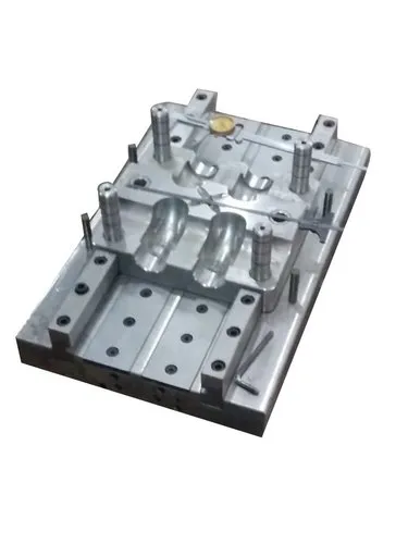
A parting line in injection moulds is the line or boundary on a moulded plastic component that is formed where two or more sections of the mould meet. It represents the separation between the mould halves or between different mould components during the injection moulding process.
The parting line is an important element of mould design because it influences the appearance, dimensional accuracy, flash formation, ease of demoulding, mould construction cost, and overall quality of the finished product.
In injection moulding, molten plastic is injected into a closed mould cavity under pressure. After the plastic cools and solidifies, the mould opens along the parting line, allowing the finished component to be removed.
A properly designed parting line helps ensure reliable mould operation, consistent product quality, and efficient manufacturing.
2. Definition of Parting Line
The parting line is the interface where the stationary and moving sections of an injection mould come together to form the mould cavity.
In a conventional two-plate mould, the two main sections are:
- Fixed half: Attached to the stationary platen of the injection moulding machine. It commonly contains the sprue and injection nozzle interface.
- Moving half: Attached to the moving platen. It commonly contains the ejection system, including ejector pins.
When the mould closes, the two halves form the cavity into which molten plastic is injected. When the mould opens, separation occurs at the parting line.
The location of this line depends on the geometry of the component, the mould construction, the position of the core and cavity, and the required demoulding direction.
3. Functions of the Parting Line
The parting line serves several important purposes in injection moulding.
3.1 Separates the mould halves
The primary function of the parting line is to define where the mould opens and closes. This allows the moulded product to be removed after cooling.
3.2 Defines the mould cavity
The parting line determines how the cavity is divided between the mould components. Its position influences the geometry that can be manufactured and the complexity of the mould.
3.3 Supports demoulding
A correctly positioned parting line helps the mould open without trapping the component. It should be selected to avoid unnecessary undercuts and difficult release conditions.
3.4 Controls flash formation
Flash is a thin layer of unwanted plastic that escapes between mould surfaces during injection.
A properly designed and maintained parting line reduces the risk of flash by providing adequate contact between the mould halves.
3.5 Influences product appearance
The parting line can leave a visible mark on the finished product. Its position should therefore be selected to minimize its effect on visible or functional surfaces.
3.6 Supports mould maintenance
A practical parting-line design allows the mould to be cleaned, inspected, repaired, and maintained more easily.
4. Types of Parting Lines in Injection Moulds
Different component geometries require different parting-line arrangements.
4.1 Flat Parting Line
A flat parting line lies on a single plane between the mould halves.
It is commonly used for simple components such as flat covers, plates, basic containers, and rectangular parts.
Advantages:
- Simple mould construction
- Relatively low manufacturing cost
- Easy machining and maintenance
- Straightforward mould opening
Limitations:
- May not suit complex component geometries
- Can leave a visible seam on the product
- May require additional mechanisms if undercuts are present
4.2 Stepped Parting Line
A stepped parting line changes direction or level rather than following one flat plane.
It is used when the product geometry requires different parting heights or when a flat parting line would create excessive flash, poor shut-off conditions, or difficult mould construction.
Advantages:
- Accommodates more complex geometries
- Can improve mould layout
- May reduce the visibility of the seam on selected surfaces
Limitations:
- More difficult to machine
- Requires accurate alignment
- May increase mould manufacturing and maintenance costs
4.3 Curved Parting Line
A curved parting line follows a curved or contoured product surface.
It is useful for components such as rounded housings, curved covers, and certain consumer-product enclosures.
Advantages:
- Can follow the natural shape of the component
- Provides flexibility in mould design
- May reduce the visibility of the seam on selected surfaces
Limitations:
- Requires more complex machining
- Demands careful alignment and fitting
- Can be more difficult to inspect and maintain
4.4 Complex or Three-Dimensional Parting Line
A complex parting line follows multiple directions or surfaces in three-dimensional space.
It may be needed for irregular housings, automotive components, and products with complex external profiles.
Advantages:
- Accommodates complex product shapes
- Offers greater flexibility in mould construction
- Can help manage complicated demoulding requirements
Limitations:
- Higher design and manufacturing complexity
- More demanding mould fitting
- Greater potential for wear or flash at poorly supported shut-off areas
5. Factors Affecting Parting-Line Selection
The location and shape of the parting line must be considered during the early stages of mould design.
5.1 Product Geometry
The overall shape, depth, curvature, ribs, bosses, holes, and undercuts of the component determine the feasible parting-line locations.
A simple component may need only a flat parting line, while a complex housing may require a stepped or contoured arrangement.
5.2 Direction of Mould Opening
The mould should generally open in a direction that allows the component to be removed without damage.
The parting line must be compatible with the opening direction, and any undercuts that prevent release must be addressed through suitable design features or additional mould mechanisms.
5.3 Product Appearance
If the component has visible cosmetic surfaces, the parting line should ideally be placed on a less noticeable edge, rear surface, or non-cosmetic area.
This is particularly important for transparent components, glossy housings, and consumer products.
5.4 Flash Prevention
The parting surfaces must fit together accurately and withstand the mould-closing and injection loads.
Insufficient contact, wear, debris, mould damage, or excessive mould deflection can create gaps that allow molten plastic to escape.
5.5 Material Properties
Different plastics have different melt viscosities, shrinkage characteristics, processing temperatures, and filling behaviours.
These properties influence the likelihood of flash and the requirements for mould sealing, venting, and cooling.
5.6 Manufacturing Cost
A simple parting line is generally easier and less expensive to machine than a complex three-dimensional parting surface.
However, the cheapest design is not always the best choice. The selected design should balance manufacturing cost, product quality, cycle time, and mould service life.
6. Parting Line and Flash Formation
One of the most important defects associated with the parting line is flash.
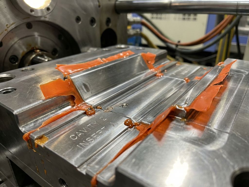
Flash occurs when molten plastic escapes through a gap between mould surfaces and solidifies as a thin, unwanted projection on the component.
Common causes include:
- Excessive injection or holding pressure
- Insufficient clamping force
- Worn or damaged parting surfaces
- Incorrect mould alignment
- Dirt or plastic residue on the parting surfaces
- Excessive mould deflection
- Inappropriate processing conditions
Prevention of flash
Flash can be minimized by:
- Ensuring accurate machining and fitting of the parting surfaces.
- Maintaining adequate mould-clamping force.
- Optimizing injection pressure and filling speed.
- Inspecting the mould regularly for wear and damage.
- Cleaning the parting surfaces before closing the mould.
- Checking mould alignment and machine condition.
- Applying suitable process settings for the selected plastic.
Increasing clamping force alone is not always the correct solution. The cause of the flash should first be identified because excessive clamping can create other problems, including mould damage and inadequate venting.
7. Parting Line and Mould Venting
During injection moulding, air inside the cavity must escape as molten plastic fills the available space.
Vents are often provided near the parting line to allow displaced air and gases to escape. These vents must be designed carefully because they need to release air without allowing excessive molten plastic to leak out.
Poor venting can cause:
- Burn marks
- Incomplete filling
- Short shots
- Poor surface finish
- Localized defects caused by trapped gas
The vent depth and width depend on the plastic material, cavity geometry, and processing conditions.
Therefore, parting-line design must balance effective air evacuation with reliable sealing against flash.
8. Parting Line and Product Quality
The parting line can affect several aspects of the finished component.
| Quality factor | Effect of parting-line design |
|---|---|
| Surface appearance | May create a visible seam or witness mark |
| Dimensional accuracy | Poor alignment can create steps or mismatch |
| Flash | Inadequate sealing can produce excess plastic |
| Demoulding | Poor positioning can cause sticking or damage |
| Surface finish | Parting-line mismatch may leave a rough edge |
| Structural quality | Defects at functional interfaces may affect assembly or performance |
| Production efficiency | Difficult parting lines can increase maintenance and cycle interruptions |
A visible parting line is not necessarily a defect. Its acceptability depends on the product specification, intended application, and permitted cosmetic tolerances.
9. Common Parting-Line Defects
9.1 Parting-Line Mismatch
Parting-line mismatch occurs when the two mould halves do not align accurately, creating a step or offset on the component.
Possible causes:
- Worn guide pins or bushes
- Incorrect mould assembly
- Misalignment of mould components
- Damage to locating surfaces
Prevention: Inspect alignment components, maintain locating surfaces, and verify mould assembly accuracy.
9.2 Excessive Flash
Excessive flash appears as a thin plastic projection along the parting line.
Possible causes:
- Excessive cavity pressure
- Insufficient clamping force
- Damaged parting surfaces
- Mould deflection
- Contamination between the mould halves
Prevention: Correct the underlying process or tooling issue and maintain proper mould contact.
9.3 Visible Witness Marks
A witness mark is a visible line or change in surface appearance where the mould halves meet.
Possible causes:
- Parting-line location on a cosmetic surface
- Surface-finish differences between mould sections
- Mould mismatch
- Wear or damage
Prevention: Select an appropriate parting-line location, maintain surface quality, and minimize mismatch.
9.4 Burrs and Sharp Edges
Burr-like projections may develop when plastic escapes through gaps or when mould edges become damaged.
Prevention: Maintain sharp, properly fitted shut-off edges where the design requires them, and inspect worn surfaces regularly.
10. Design Guidelines for an Effective Parting Line
A well-designed parting line should follow these principles:
- Choose a suitable location: Place the parting line where it will have the least negative effect on product function and appearance.
- Minimize complexity: Prefer a simple parting surface when product geometry permits.
- Consider demoulding: Ensure the component can be released in the intended mould-opening direction.
- Avoid unnecessary undercuts: Reduce the need for slides, lifters, or other complex mechanisms where practical.
- Maintain adequate sealing: Design robust parting surfaces to resist injection pressure.
- Provide suitable venting: Allow trapped air to escape without creating excessive flash.
- Account for shrinkage: Consider material shrinkage and dimensional tolerances during cavity and core design.
- Facilitate maintenance: Ensure the parting surfaces can be accessed for inspection, cleaning, and repair.
- Protect cosmetic surfaces: Keep the seam away from highly visible areas when possible.
- Validate the design: Use mould-flow analysis, design reviews, and production trials where appropriate.
11. Example of Parting-Line Selection
Consider a plastic rectangular enclosure with a top cover and a base.
If the enclosure has a relatively simple geometry, the parting line may be placed around the perimeter of the enclosure. This allows the cavity to form the outer surfaces while the core forms the internal features.
For a product with a highly visible front face, the parting line may be positioned along a side edge or rear surface to reduce its visual impact.
If the enclosure contains side openings or undercuts, additional mould mechanisms may be necessary. In this situation, the parting-line location must be considered together with the slide directions, core layout, ejection system, and mould-opening sequence.
This example demonstrates that parting-line selection is not merely a geometric decision; it is a compromise between product design, tool construction, moulding performance, and cost.
12. Inspection and Maintenance
Regular inspection of the parting line is essential for consistent production quality.
Maintenance activities should include:
- Cleaning the parting surfaces.
- Checking for scratches, dents, corrosion, and wear.
- Inspecting guide pins, bushes, and locating components.
- Checking for parting-line mismatch.
- Monitoring flash and witness marks on moulded products.
- Repairing damaged shut-off surfaces.
- Verifying mould alignment after maintenance.
Preventive maintenance helps reduce unplanned downtime, product rejection, and expensive mould repairs.
Conclusion
The parting line in injection moulds is the boundary where the mould sections meet and separate during the production cycle. Its design influences mould opening, component removal, surface appearance, dimensional accuracy, venting, flash formation, and overall manufacturing efficiency.
An effective parting-line design should be based on product geometry, mould-opening direction, material properties, cosmetic requirements, manufacturing cost, and ease of maintenance.
By selecting an appropriate parting-line location, ensuring accurate mould alignment, providing effective venting, and maintaining the sealing surfaces, manufacturers can reduce defects and improve the consistency and quality of injection-moulded components.