1. Introduction
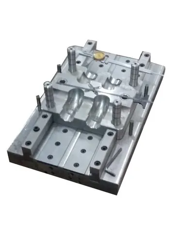
Vent design in compression moulding is the process of providing small openings or controlled clearances in a mould so that trapped air, gases, moisture vapour, and volatile substances can escape during mould closing and material compression.
Compression moulding is commonly used to manufacture components from thermosetting plastics, rubber, composite materials, and certain thermoplastic compounds. During moulding, the material is placed inside a heated mould, and pressure is applied to force it into the cavity.
As the mould closes, air can become trapped between the moulding material and the cavity surfaces. If this air cannot escape, it may cause surface defects, incomplete filling, internal voids, or local burning.
Proper vent design helps produce components with better surface quality, more complete filling, and consistent dimensions.
2. What Is a Vent in Compression Moulding?
A mould vent is a narrow passage or clearance that allows air and gases to escape from the cavity while restricting the flow of moulding material.
Vents are generally located near cavity edges, material flow fronts, corners, deep sections, and other locations where air is likely to become trapped.
The vent must be large enough to release gases but sufficiently restrictive to prevent excessive material leakage, commonly called flash.
The correct vent dimensions depend on the material, viscosity, moulding pressure, temperature, cavity geometry, and material’s tendency to flash.
3. Functions of Venting in Compression Moulding
The main functions of venting include:
- Air removal: Releases air trapped inside the mould cavity.
- Gas evacuation: Allows gases produced during heating and curing to escape.
- Improved cavity filling: Helps the moulding compound spread into narrow sections and detailed features.
- Defect prevention: Reduces the risk of burns, voids, blisters, and incomplete moulding.
- Improved surface quality: Helps prevent surface imperfections caused by trapped gases.
- Process consistency: Reduces variations between moulded components.
- Improved material consolidation: In suitable processes, venting or vacuum-assisted evacuation can reduce trapped air within the moulding material.
Venting alone cannot eliminate all internal porosity. Material preparation, moisture control, charge placement, and moulding parameters also influence the final result.
4. Types of Vents Used in Compression Moulding
4.1 Parting-Line Vents
Parting-line vents are formed along the interface between the two mould halves.
They are commonly used because the parting line provides a convenient location for gases to escape.
Advantages:
- Simple to manufacture.
- Relatively easy to inspect and clean.
- Suitable for many conventional compression moulds.
Limitations:
- Excessive clearance can produce flash.
- Their effectiveness depends on the cavity geometry and where air becomes trapped.
- They may not adequately vent isolated pockets or deep recesses.
4.2 Shallow Vent Grooves
Shallow grooves are machined into selected mould surfaces or parting-line areas to create a controlled gas escape path.
They can be positioned near cavity extremities, corners, ribs, and other regions where trapped air is expected.
Their depth, width, and length must be selected carefully to balance gas flow against material leakage.
4.3 Edge Vents
Edge vents are placed near the outer boundaries of the mould cavity, where air tends to accumulate as the material spreads outward.
They are particularly useful when the moulding compound flows from a central charge toward the cavity edges.
Their placement should follow the expected material flow pattern rather than simply being distributed evenly around the entire cavity.
4.4 Pin or Insert Vents
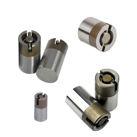
These vents use a specially designed pin or insert to create a gas escape route.
They may be useful in complex moulds where conventional parting-line venting is insufficient.
Their design must avoid creating unwanted witness marks, weak areas, or excessive material leakage.
4.5 Porous Vent Inserts
Porous inserts allow gases to pass through interconnected pores while restricting bulk material flow.
They can be useful in complex cavities or areas where conventional vent grooves are difficult to place.
However, porous inserts require suitable material selection, careful installation, and regular cleaning because their pores can become blocked by resin, release agents, or moulding residue.
4.6 Vacuum-Assisted Venting
Vacuum-assisted systems remove air from the cavity before or during mould closing.
A vacuum port, sealing arrangement, and vacuum source are used to reduce the amount of trapped air.
Vacuum assistance can be particularly valuable for complex parts, fibre-reinforced composites, and applications requiring low porosity. It does not replace proper charge placement and vent-path design.
5. Principles of Vent Design
5.1 Vent Depth
Vent depth is one of the most critical design parameters.
If the vent is too shallow, air may not escape quickly enough. If it is too deep, the moulding compound may enter the vent and produce excessive flash.
The appropriate depth depends strongly on the material:
- Low-viscosity compounds may flow into very small clearances.
- High-viscosity compounds may tolerate different vent geometries.
- Rubber compounds may require different venting strategies from rigid thermosetting materials.
- Fibre-reinforced compounds may behave differently from unfilled resin systems.
There is no single vent depth suitable for all compression moulding materials. The final dimensions should be based on material supplier recommendations, moulding trials, and quality requirements.
5.2 Vent Width
Vent width affects the total area available for gas escape.
A wider vent can increase gas-flow capacity, but it may also increase the chance of material leakage. Vent width must therefore be considered together with depth, length, and the number of vents.
5.3 Vent Length
The vent land is the short, restrictive section through which gas passes before entering a larger escape channel.
A controlled vent land can help restrict moulding material while allowing gases to escape. The passage beyond the land should provide enough clearance for gases to leave the mould without being obstructed.
5.4 Vent Location
Correct placement is essential because a well-sized vent is ineffective if it is not located where air accumulates.
Common vent locations include:
- Cavity extremities.
- Corners and recesses.
- The ends of ribs and narrow channels.
- Areas opposite the initial material charge.
- Locations where multiple flow fronts meet.
- Regions known to produce burns or incomplete filling.
5.5 Number of Vents
The number of vents depends on the cavity shape, material flow, and expected gas generation.
Simple cavities may require only a few strategically placed vents, while complex cavities may need multiple vent paths or vacuum assistance.
Adding vents indiscriminately is not always beneficial because it can create flash, increase cleaning requirements, and weaken local cavity edges.
6. Vent Design for Different Compression Moulding Materials
| Material | Main venting consideration |
|---|---|
| Phenolic compounds | Gas evacuation and prevention of local burning |
| Epoxy moulding compounds | Control of trapped air and gases during cure |
| Unsaturated polyester compounds | Release of trapped air and volatile substances |
| Silicone rubber | Preventing air pockets in thin sections and complex features |
| General rubber compounds | Evacuation of air and gases generated during vulcanisation |
| Fibre-reinforced composites | Air removal and control of porosity while preserving fibre placement |
The exact vent design must be validated for the specific compound, curing cycle, pressure, and mould geometry.
7. Common Venting Defects and Their Causes
7.1 Burn Marks
Burn marks may occur when trapped air or gases become compressed and heated, causing local surface discolouration or degradation.
Possible solutions:
- Add or reposition vents near the affected area.
- Clean existing vent passages.
- Review charge placement and material distribution.
- Check mould temperature, closing speed, and curing conditions.
7.2 Incomplete Filling
Incomplete filling occurs when material cannot reach all areas of the cavity.
Trapped air can contribute to this problem, but other causes include insufficient charge material, unsuitable material flow characteristics, inadequate temperature, or insufficient pressure.
Possible solutions:
- Improve vent placement.
- Review charge size and distribution.
- Verify material temperature and mould temperature.
- Check the mould closing and pressure sequence.
7.3 Excessive Flash
Flash is a thin layer of excess material that escapes through the parting line or vent openings.
Possible solutions:
- Reduce vent depth or adjust the vent land where appropriate.
- Inspect the mould parting surfaces for wear or damage.
- Verify mould closing pressure and alignment.
- Review material viscosity and charge quantity.
Reducing vent dimensions without identifying the root cause may worsen trapped-air defects.
7.4 Internal Voids
Voids are cavities within the moulded component. They may result from trapped air, volatile release, poor material consolidation, or shrinkage during curing.
Possible solutions:
- Improve vent paths or use vacuum assistance.
- Control moisture and material storage.
- Optimise charge placement and mould-closing sequence.
- Review curing and pressure conditions.
7.5 Surface Blisters
Blisters may form when trapped gases or vapours create local separation or swelling within the material.
Possible solutions:
- Check material moisture and storage conditions.
- Improve venting and gas evacuation.
- Review the heating and curing profile.
- Verify that the charge is distributed correctly.
8. Vent Design Procedure
A systematic approach helps produce reliable venting.
- Study the component geometry. Identify corners, recesses, thin sections, and likely air-trapping regions.
- Understand material behaviour. Review viscosity, cure characteristics, gas generation, and the material supplier’s recommendations.
- Predict material flow. Determine where the charge begins to spread and where flow fronts are likely to meet.
- Select vent locations. Position vents near likely air-trapping areas and cavity extremities.
- Determine vent geometry. Select suitable depth, width, vent-land length, and escape-channel dimensions.
- Check mould strength. Ensure the vent does not compromise critical sealing surfaces or mould edges.
- Run moulding trials. Inspect the component for burns, flash, voids, incomplete filling, and surface defects.
- Optimise the design. Adjust vent geometry and process conditions based on trial results.
- Document the final design. Record dimensions, locations, material type, and validated process settings.
9. Maintenance of Mould Vents
Vents can become blocked by cured resin, rubber residue, release agents, and other contaminants. Blocked vents reduce gas flow and can lead to recurring defects.
Recommended maintenance practices include:
- Inspect vents regularly for blockages and wear.
- Clean vent grooves using approved tools and methods.
- Avoid abrasive cleaning that changes vent dimensions.
- Check parting surfaces for damage or deformation.
- Verify vacuum ports, hoses, and seals in vacuum-assisted systems.
- Record recurring defects and the maintenance performed.
Vent cleaning should restore the intended geometry without enlarging the vent or damaging the mould surface.
10. Advantages of Proper Vent Design
Proper vent design can provide:
- Fewer burn marks and gas-related defects.
- More complete cavity filling.
- Better surface finish.
- Reduced internal porosity in suitable processes.
- Less rework and scrap.
- More consistent component quality.
- Greater process reliability.
However, venting must be combined with correct material preparation, charge placement, temperature, pressure, and curing time.
Conclusion
Vent design is an essential part of compression mould design because it allows trapped air and gases to escape while the material fills and cures inside the cavity.
The most important design factors are vent depth, width, length, location, and the number of vents. These must be selected according to the material’s flow and curing behaviour, the component geometry, and the moulding conditions.
A well-designed and properly maintained venting system helps prevent burn marks, incomplete filling, flash, blisters, and voids, improving the overall quality and consistency of compression-moulded components.