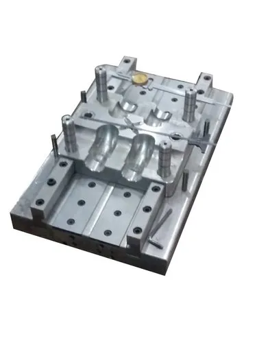
Ejector systems are essential components of injection moulds used in plastic manufacturing. Their primary function is to remove the moulded plastic part from the mould cavity after the plastic has cooled and solidified. A properly designed ejector system ensures smooth part removal, reduces the risk of damage, improves production efficiency, and supports consistent product quality.
During injection moulding, molten plastic is injected into a mould under pressure. After cooling, the plastic part becomes solid and may shrink around the core. The ejector system applies a controlled force to separate the finished component from the mould without causing deformation, scratches, or breakage.
Different types of ejector systems are selected according to the product’s shape, size, material, wall thickness, and mould design.
1. Pin Ejector System
The pin ejector system is one of the most widely used ejection methods in injection moulding. It uses cylindrical steel pins positioned at specific locations behind the moulded component.
When the mould opens, the ejector plate moves forward and pushes the ejector pins against the plastic part. The pins then push the part away from the core.
Advantages:
- Simple construction and cost-effective design.
- Suitable for many common plastic components.
- Easy to manufacture, maintain, and replace.
- Provides reliable ejection when pins are positioned correctly.
Applications: Plastic caps, housings, containers, electronic components, and general-purpose plastic parts.
Limitation: Ejector pins may leave small circular marks on the product surface. Their placement must be carefully planned to prevent marks, bending, or cracking.
2. Sleeve Ejector System
A sleeve ejector system uses a hollow cylindrical sleeve that moves around a fixed core pin. Instead of applying force through a small pin, the sleeve distributes ejection force over a larger circular area.
When the mould opens, the sleeve advances and pushes the moulded component away from the core.
Advantages:
- Distributes force more evenly around circular features.
- Reduces concentrated stress on the component.
- Suitable for parts with central holes or cylindrical shapes.
- Can improve ejection stability.
Applications: Plastic bushings, cylindrical caps, gear hubs, round connectors, and components with central bosses.
Limitation: Sleeve ejectors require accurate alignment and suitable clearances between the sleeve and core pin to prevent wear or sticking.
3. Blade Ejector System
Blade ejectors use thin, flat ejector elements instead of round pins. They are particularly useful for ejecting narrow ribs, thin walls, and elongated features where conventional round pins may not fit.
The blade moves forward with the ejector plate and pushes against a suitable surface of the moulded part.
Advantages:
- Fits into narrow spaces.
- Provides support along a longer, narrow contact area.
- Useful for parts with thin ribs or elongated sections.
Applications: Plastic clips, thin ribs, rectangular slots, narrow projections, and certain automotive or electronic components.
Limitation: Blade ejectors can bend, wear, or break if they are too thin or incorrectly supported. Proper material selection and alignment are important.
4. Stripper Plate Ejector System
A stripper plate system uses a specially designed plate to push the moulded component away from the core. Instead of using individual pins at multiple points, the plate contacts a larger portion of the product.
When the mould opens, the stripper plate moves and separates the component from the core.
Advantages:
- Provides broad and relatively uniform ejection force.
- Reduces visible pin marks on the ejected surface.
- Suitable for thin-walled or large circular components.
- Helps reduce local stress and deformation.
Applications: Plastic bowls, containers, lids, buckets, cups, and circular thin-walled products.
Limitation: The system may require more complex mould construction, precise guiding, and additional space. It is not suitable for every product geometry.
5. Air Ejector System
An air ejector system uses compressed air to help separate a moulded component from the core or mould surface. Air is introduced through specially designed ports or passages to reduce the vacuum or adhesion that can hold the part in place.
Air ejection is often used together with mechanical ejector systems rather than as a complete replacement.
Advantages:
- Reduces sticking caused by vacuum effects.
- Minimizes contact marks on visible surfaces.
- Useful for certain thin-walled or large surface-area components.
- Can assist in releasing parts that fit tightly around the core.
Applications: Thin-walled containers, lids, selected packaging components, and parts with large contact surfaces.
Limitation: Air pressure and port positions must be carefully controlled. Poorly designed air passages may cause uneven release, deformation, or safety concerns.
6. Two-Stage Ejector System
A two-stage ejector system releases the moulded part in two successive movements. The first movement may release the component partially, while the second movement completes ejection or separates the part from a particular mould feature.
The sequence can be controlled mechanically or through a suitable mould and machine arrangement.
Advantages:
- Supports controlled ejection of complex components.
- Helps release parts with deep cores or difficult geometries.
- Can reduce the risk of damage during removal.
- Allows different ejector elements to move in a planned sequence.
Applications: Deep containers, complex housings, components with internal features, and moulds requiring staged release.
Limitation: The mechanism is more complicated than a conventional pin ejector system and requires accurate timing, adjustment, and maintenance.
7. Lifter Ejector System
A lifter system is designed to release moulded components containing undercuts on internal or external surfaces. An undercut is a feature that prevents the part from being pulled straight out of the mould.
During ejection, the lifter moves forward and sideways, or along an angled path, to clear the undercut before the component is removed.
Advantages:
- Enables moulding of certain undercut features without separate manual removal.
- Supports automated production.
- Can reduce the need for additional side mechanisms in suitable designs.
Applications: Plastic clips, snap-fit components, housings with internal hooks, and products with angled internal features.
Limitation: Lifter movement requires precise design and guidance. Excessive friction, incorrect angles, or insufficient clearance can cause wear and ejection problems.
8. Hydraulic Ejector System
A hydraulic ejector system uses hydraulic power to move the ejector plate or ejector mechanism. It may be controlled by the injection moulding machine or by a dedicated hydraulic arrangement, depending on the equipment.
Hydraulic systems are useful when an application requires a controlled force or a specific ejection stroke.
Advantages:
- Provides substantial force when properly sized.
- Can support controlled movement and adjustable strokes.
- Useful for some large moulds and specialised applications.
Applications: Large plastic components, industrial moulding systems, and specialised moulds requiring hydraulic actuation.
Limitation: Hydraulic systems need suitable hoses, seals, fluid management, and maintenance. Leakage or incorrect pressure settings can affect operation.
9. Mechanical Ejector System
Mechanical ejector systems use physical mechanisms such as rods, cams, levers, springs, or linkages to produce the movement required for ejection. The exact arrangement depends on the mould design and the required sequence of motion.
Advantages:
- Can operate without a dedicated hydraulic actuator for the ejection movement.
- Suitable for specific sequencing requirements.
- Can be integrated into specialised mould designs.
Applications: Special-purpose moulds, staged ejection arrangements, and mechanisms requiring coordinated mechanical movement.
Limitation: Mechanical parts must be designed to withstand repeated loads. Wear, incorrect adjustment, or insufficient lubrication may affect performance.
10. Spring-Assisted Ejector System
Spring-assisted ejector systems use springs to provide or assist a return force for ejector components. Springs are commonly incorporated into the return mechanism rather than used as the sole source of ejection force.
After the moulded part is removed, the springs help return the ejector mechanism to its original position.
Advantages:
- Can simplify the return arrangement in suitable designs.
- Provides a repeatable return force.
- May reduce the need for additional return components in some applications.
Applications: Small moulds, selected ejector return arrangements, and mechanisms where spring force is appropriate.
Limitation: Springs can lose force through fatigue or wear. They must be correctly sized and should not be relied on where positive, machine-controlled return is required for safety or reliable operation.
Comparison of Ejector Systems
| Ejector system | Main function | Typical applications |
|---|---|---|
| Pin ejector | Pushes the part using individual pins | General plastic components |
| Sleeve ejector | Pushes around a circular feature | Bushings, round caps, hubs |
| Blade ejector | Pushes through narrow contact areas | Thin ribs, clips, narrow features |
| Stripper plate | Pushes over a larger surface area | Cups, lids, containers |
| Air ejector | Uses air to assist release | Thin-walled and large-area parts |
| Two-stage ejector | Releases the part in successive movements | Complex or deep components |
| Lifter ejector | Clears undercuts during ejection | Snap-fits and hooked features |
| Hydraulic ejector | Uses hydraulic power for movement | Large or specialised moulds |
| Mechanical ejector | Uses linkages or other mechanisms | Special-purpose moulds |
| Spring-assisted ejector | Assists ejector return or movement | Selected small or specialised moulds |
Factors to Consider When Selecting an Ejector System
Choosing the correct ejector system is essential for reliable mould operation. The following factors should be considered:
- Product geometry: Deep sections, ribs, holes, undercuts, and complex shapes may require different ejection methods.
- Plastic material: Flexible, rigid, brittle, and high-shrinkage materials behave differently during ejection.
- Wall thickness: Thin-walled parts may deform if the ejection force is concentrated in a small area.
- Surface finish: Products with high-quality visible surfaces may benefit from stripper plates or carefully positioned ejector pins.
- Ejection force: The system must overcome friction, shrinkage grip, and other forces holding the part in the mould.
- Production speed: High-volume production requires consistent, repeatable ejection with minimal downtime.
- Mould complexity and cost: More complex systems can improve part release but may increase manufacturing and maintenance costs.
- Automation requirements: The ejector arrangement should support reliable removal and the intended production cycle.
Common Ejector System Problems
Incorrect ejector design or maintenance can lead to several production issues:
- Ejector marks: Caused by excessive local pressure or poor pin placement.
- Part deformation: Occurs when the component is still too soft or ejection forces are uneven.
- Part sticking: Can result from insufficient draft, excessive shrinkage grip, surface damage, or inadequate cooling.
- Pin breakage: May occur due to misalignment, excessive load, or inadequate support.
- Uneven ejection: Can result from incorrect ejector positioning or inconsistent movement.
- Slow production cycles: May occur when the ejection mechanism requires excessive time or frequent adjustment.
These problems can often be reduced by optimising ejector placement, providing adequate draft angles, maintaining appropriate cooling, ensuring proper alignment, and carrying out regular mould maintenance.
Conclusion
Ejector systems play a vital role in injection moulding because they ensure that finished plastic components can be removed safely and efficiently. Pin, sleeve, blade, stripper plate, air, two-stage, lifter, hydraulic, mechanical, and spring-assisted systems each serve different purposes.
The best choice depends on the component’s geometry, material, surface requirements, production volume, and mould construction. A well-designed ejector system improves product quality, reduces cycle interruptions, extends mould service life, and supports efficient manufacturing.