Injection moulding is a widely used manufacturing process for producing plastic components in high volumes. While the process is highly efficient, it is also prone to defects that can compromise the quality, appearance, and functionality of the final product. Many of these defects are directly related to the design, condition, or maintenance of the mould (die). Understanding these die-related causes is essential for minimizing scrap rates and improving production efficiency.
1. Short Shots
Description:
A short shot occurs when the molten plastic does not completely fill the mould cavity, resulting in an incomplete part.
Die-Related Causes:
Inadequate Venting: Poor air venting in the mould prevents displaced air from escaping, creating back pressure.
Flow Restrictions: Narrow or improperly designed gates, runners, or sprues limit material flow.
Cold Die Temperature: If the die is too cold, the molten plastic solidifies prematurely.
Improper Gate Location: Poor gate placement can result in uneven flow and insufficient cavity fill.
2. Flash
Description:
Flash is excess material that escapes from the mould cavity and solidifies along the parting line or around ejector pins.
Die-Related Causes:
Worn or Damaged Parting Line: Gaps due to wear or poor alignment allow material to escape.
Excessive Clamping Force Misalignment: Improper alignment or worn clamping surfaces may result in uneven closing of the mould.
Incorrect Ejector Pin Fit: Loose ejector pins may allow resin to leak around them.
Improper Venting: Excess pressure can force molten plastic into unintended areas if the vents are too deep or too numerous.
3. Sink Marks
Description:
Sink marks are small depressions or dimples on the surface of the moulded part, usually in thicker sections.
Die-Related Causes:
Improper Cooling Design: Inadequate or uneven cooling can lead to differential shrinkage.
Thick Wall Sections: Mould design that includes thick areas can exacerbate shrinkage.
Inconsistent Cavity Pressure: Poor cavity balancing can lead to localized sink marks.
Lack of Venting: Poor venting can also reduce cavity pressure and promote sink formation.
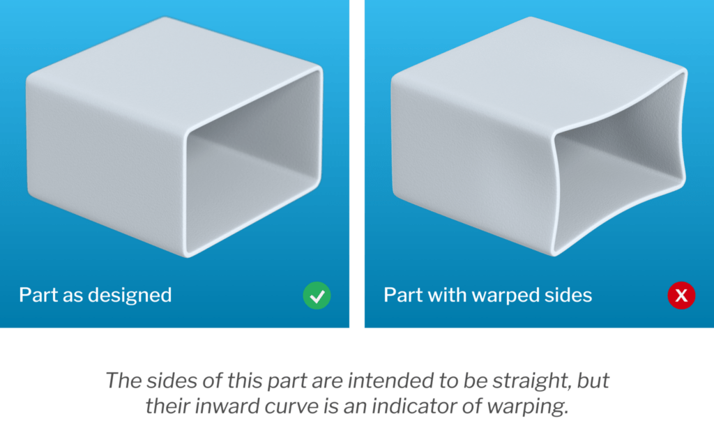
4. Warping and Distortion
Description:
Warping refers to bending or twisting of the part after ejection due to uneven shrinkage.
Die-Related Causes:
Uneven Cooling Channels: Poorly designed or asymmetrical cooling leads to uneven solidification.
Non-Uniform Wall Thickness: Die design that results in varying wall thickness causes inconsistent shrinkage.
Improper Ejection System: Uneven ejection force can bend or stress the part during removal.
5. Weld Lines (Knit Lines)
Description:
Weld lines occur where two flow fronts of molten plastic meet but do not fuse properly, resulting in a visible line or weakness.
Die-Related Causes:
Improper Gate Location: Gates placed far from meeting flow fronts create weak weld lines.
Complex Geometry: Features like holes or inserts in the die can cause flow to split and rejoin.
Inadequate Venting: Entrapped air at the meeting point can interfere with proper fusion.
Cold Die Surface at Weld Area: If the weld area in the die is too cold, the fronts won’t fuse completely.
6. Burn Marks (Diesel Effect)
Description:
Burn marks are black or brown discolorations on the part surface, caused by trapped air or gases burning.
Die-Related Causes:
Inadequate Venting: Trapped gases or air heat up and ignite, leaving burn marks.
Fast Injection Speed: High-speed flow in a poorly vented mould can compress air rapidly.
Incorrect Gate Design: Gates that direct flow into confined areas can trap air.
7. Jetting
Description:
Jetting appears as snake-like, wavy lines on the part caused by the initial jet of molten plastic entering the cavity at high speed.
Die-Related Causes:
Improper Gate Design or Position: Small or poorly positioned gates cause high-velocity jets instead of smooth flow.
Long Flow Paths Without Gradual Transition: Sudden changes in cavity cross-section cause jetting.
8. Voids and Air Traps
Description:
Voids are internal pockets of air that form within the moulded part, affecting structural integrity.
Die-Related Causes:
Insufficient Venting: Trapped air has no escape route.
Uneven Cooling or Thick Sections: Differential cooling causes shrinkage that pulls air inward.
Mould Geometry: Poor design with complex flow paths can lead to localized air pockets.
9. Ejector Marks and Damage
Description:
Ejector marks are blemishes or deformations on the part surface caused during the ejection phase.
Die-Related Causes:
Improper Ejector Pin Design or Placement: Incorrect size, location, or number of ejector pins can cause stress marks.
Uneven Ejection Force: Poor ejection balance leads to part deformation.
Insufficient Draft Angles: Low or no draft makes parts stick to the core, requiring excessive force to eject.
10. Delamination
Description:
Delamination is the separation of thin layers on the surface, giving a flaky appearance.
Die-Related Causes:
Contaminants in Die Surfaces: Foreign material in the die can mix with the melt and separate.
Incorrect Mould Surface Finish: Rough or improperly treated surfaces can interfere with material flow.
Conclusion
Most injection moulding defects can be minimized or eliminated by addressing die-related issues. Proper die design, maintenance, venting, gate placement, and cooling system configuration are essential for achieving high-quality moulded parts. Regular inspection and optimization of the die can dramatically improve product consistency, reduce cycle times, and lower production costs.