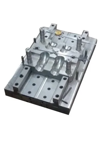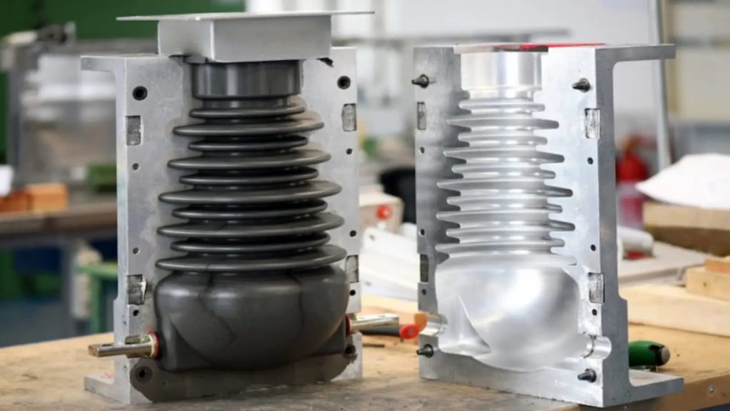
A compression mould is a tooling system used to shape materials by placing a measured charge into a mould cavity and applying heat and pressure. Compression moulds are commonly used for thermoset plastics, rubber, silicone, composites, and other moulding materials.
A typical compression mould consists of several components that work together to form, cure, cool, and remove the finished part.
1. Upper Mould Half
The upper mould half is the top section of the mould. It moves toward the lower mould half during the compression cycle.
It may contain:
- Upper cavity or core features
- Heating elements
- Guide components
- Venting features
2. Lower Mould Half
The lower mould half is usually the stationary or supporting section.
It commonly contains:
- Mould cavity
- Supporting plates
- Heating or cooling systems
- Ejection components
3. Cavity
The cavity is the shaped area that determines the external geometry of the moulded product.
Its dimensions must account for:
- Material shrinkage
- Required tolerances
- Surface finish
- Parting line
- Material flow
4. Core
The core forms internal features such as holes, recesses, channels, or hollow sections.
Depending on the product design, the core may be fixed or removable.
5. Parting Surface
The parting surface is where the mould halves meet.
A properly designed parting surface helps:
- Define the moulded shape
- Control flash
- Maintain alignment
- Allow easy mould opening
6. Guide Pins and Bushes
Guide pins and guide bushes ensure that the upper and lower mould sections align correctly.
They help prevent:
- Misalignment
- Cavity damage
- Uneven part dimensions
- Excessive mould wear
7. Heating System
Many compression moulds require controlled heating, especially for thermoset materials and rubber.
Heating may be provided through:
- Electrical cartridge heaters
- Heating plates
- Oil circulation
- Steam systems
The heating system helps maintain the required mould temperature during curing.
8. Cooling System
Some compression moulds include cooling channels or passages.
Cooling helps:
- Control cycle time
- Reduce thermal distortion
- Stabilize dimensions
- Prepare the moulded part for safe removal
9. Ejector System
The ejector system removes the finished product from the mould after curing or cooling.
It may include:
- Ejector pins
- Ejector plates
- Stripper plates
- Hydraulic or mechanical ejectors
The ejection system should remove the part without damaging its surfaces or edges.
10. Vents
Vents allow trapped air, gases, and volatiles to escape from the mould cavity.
Proper venting helps prevent:
- Air traps
- Burn marks
- Incomplete filling
- Surface defects
Vents are particularly important when materials release gases during curing.
11. Flash Land
The flash land is the controlled area around the cavity where excess material can escape as flash.
A properly designed flash land helps control:
- Flash thickness
- Material flow
- Mould sealing
- Ease of flash removal
12. Mould Plates
Mould plates provide structural support and hold different mould components together.
Common plates include:
- Top plate
- Bottom plate
- Cavity plate
- Core plate
- Support plate
- Ejector plate
13. Pressure/Clamping Surfaces
These surfaces transfer the compression force from the moulding machine to the mould.
They must be strong and accurately machined to withstand repeated high loads.
14. Insulation
Thermal insulation may be placed between heated mould sections and the machine structure.
Its purpose is to:
- Reduce heat loss
- Improve temperature stability
- Reduce energy consumption
- Protect surrounding machine components
15. Surface Finish
The cavity and core surfaces are finished according to the desired appearance of the product.
Depending on the application, the mould surface may be:
- Polished
- Textured
- Matte
- Etched
- Coated
Surface finish can also influence demoulding and product appearance.
Component Summary
| Component | Main Function |
|---|---|
| Upper mould half | Forms the upper side of the product |
| Lower mould half | Supports and forms the lower side |
| Cavity | Forms external features |
| Core | Forms internal features |
| Parting surface | Separates the mould halves |
| Guide pins & bushes | Maintain alignment |
| Heating system | Provides controlled mould temperature |
| Cooling system | Controls cooling and cycle time |
| Ejector system | Removes the finished part |
| Vents | Releases air and gases |
| Flash land | Controls excess material |
| Mould plates | Support mould components |
| Clamping surfaces | Transfer compression force |
| Insulation | Reduces unwanted heat loss |
| Surface finish | Provides required product texture |
Important Design Considerations
When designing a compression mould, engineers should pay attention to:
- Parting line location
- Draft angle
- Material shrinkage
- Cavity and core dimensions
- Flash control
- Venting
- Heating and cooling
- Ejection
- Alignment
- Mould material
- Surface finish
- Required pressure and temperature
In Short
The main components of a compression mould are the upper and lower mould halves, cavity, core, parting surface, guide system, heating/cooling system, vents, flash land, ejectors, and supporting plates.
Together, these components ensure that the material is properly positioned, compressed, heated or cured, cooled, and safely removed to produce a consistent finished product.