The cooling system in an injection mould is a critical component that significantly influences cycle time, product quality, dimensional accuracy, and overall productivity. Proper cooling system design ensures efficient heat removal from the moulded part, reducing warpage, sink marks, and residual stresses.
Objectives of Cooling System Design
Reduce Cycle Time: Efficient cooling leads to faster solidification, minimizing moulding cycles.
Ensure Uniform Cooling: Avoids differential shrinkage and warping by keeping temperature distribution uniform.
Improve Product Quality: Reduces defects like sink marks, warpage, and residual stresses.
Increase Mould Life: Prevents thermal fatigue and cracking of mould components.
Types of Cooling Systems in Injection Moulds
Conventional Cooling
Uses straight drilled channels near the mould cavity.
Easy to manufacture but may not provide uniform cooling for complex geometries.
Baffle and Bubblers
Baffles: Thin metal plates inserted into cooling channels to split water flow and improve heat transfer.
Bubblers: Tubes used to direct coolant into deep cores where direct channeling isn’t possible.
Conformal Cooling
Follows the contour of the mould cavity using advanced manufacturing like 3D printing (DMLS).
Provides superior cooling uniformity, especially for complex parts.
Helical Cooling Channels
Helical coils are used to provide continuous and uniform cooling around cores or cylindrical parts.
Often used in cap moulds or tubular products.
Design Considerations
Channel Placement
Ideally 1.5 to 2 times the diameter of the cooling channel away from the cavity surface.
Channels should be uniformly spaced and avoid sharp corners to reduce flow resistance.
Channel Diameter
Typically ranges from 6 mm to 12 mm depending on the size of the mould.
Larger diameters reduce pressure loss but may result in slower coolant velocity.
Flow Rate and Velocity
Recommended water velocity: 0.5 to 2 m/s.
Sufficient flow ensures turbulent flow for effective heat transfer.
Temperature Control
Use of temperature controllers or chillers to maintain a stable coolant temperature.
Multi-zone cooling may be needed for large or complex parts.
Material Selection
Mould materials should have high thermal conductivity (e.g., Beryllium Copper inserts) for fast heat dissipation.
Corrosion-resistant materials for cooling channels increase mould longevity.
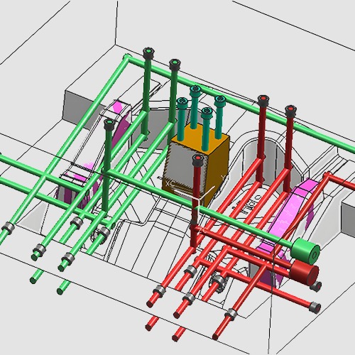
Common Cooling Channel Layouts
Parallel Circuit: All channels have the same inlet and outlet pressure. Simplifies design but can lead to uneven flow.
Series Circuit: Water flows through one channel after another. Easy to build but temperature rises progressively.
Hybrid Circuit: Combines parallel and series designs to balance flow and temperature.
Advanced Cooling Technologies
3D Printed Conformal Cooling: Allows precise and close-to-surface channel routing.
Heat Pipes: Passive heat transfer devices used in localized hot spots.
High Thermal Conductivity Inserts: Inserts made from materials like copper alloys used in areas with poor cooling access.
Simulation and Analysis
Mould Flow Analysis: Software like Moldex3D, Autodesk Moldflow, or Simcon used to simulate cooling performance.
Thermal Simulation: Helps predict temperature distribution and optimize channel layout before manufacturing.
Challenges in Cooling System Design
Complex part geometries can limit effective channel placement.
Balancing cost and performance, especially with conformal cooling.
Maintenance issues like scale or blockage in cooling channels.
Risk of thermal stresses and cracks due to improper design.
Conclusion
Effective cooling system design in injection moulds is essential for achieving high productivity, dimensional accuracy, and consistent product quality. The design must consider the part geometry, mould material, and production requirements. Innovations such as conformal cooling and simulation tools are revolutionizing the way cooling systems are optimized, making them more efficient and tailored to specific applications.