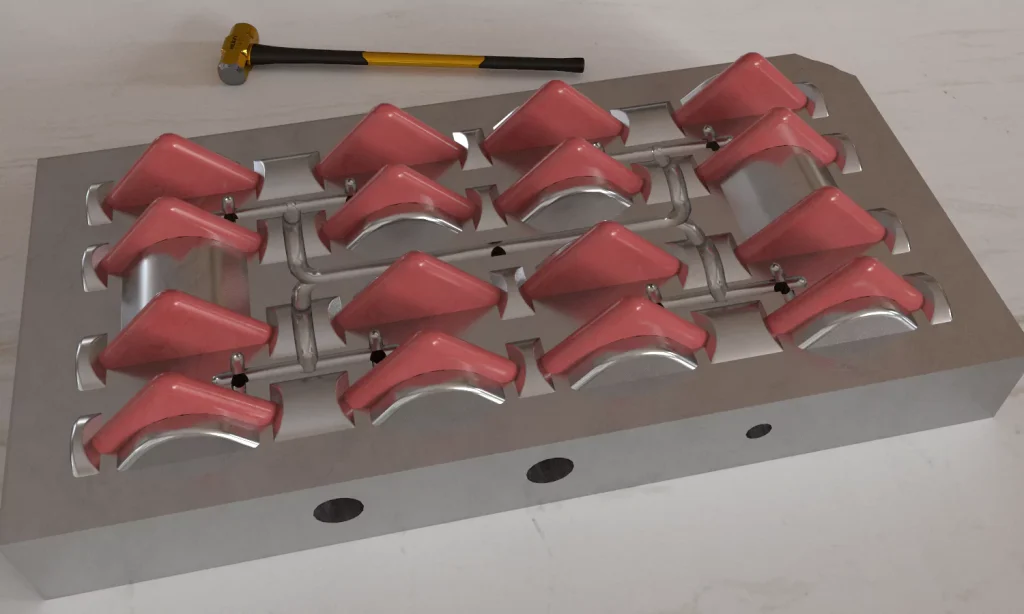
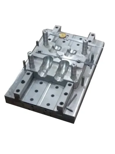
In injection molding and other tooling-based manufacturing processes, the design of the core and cavity plays a critical role in ensuring the part quality, manufacturability, and tool longevity. The core and cavity are the two halves of a mold: the core typically forms the internal features of the part, while the cavity forms the external features. Thoughtful design considerations for both are essential for optimizing the mold performance.
1. Parting Line Location
The parting line is where the core and cavity meet.
Choosing the correct location minimizes flash, simplifies machining, and enhances the appearance of the molded part.
It should be placed where it does not interfere with functional or aesthetic requirements.
2. Draft Angle
Tapered surfaces (draft angles) are added to allow easy ejection of the part.
Cavity sides usually require more draft than the core.
A typical draft angle ranges from 0.5° to 2°, depending on the material and surface finish.
3. Shrinkage Compensation
Plastics shrink as they cool; this must be considered in both core and cavity dimensions.
The core may shrink into the part, while the cavity affects external dimensions.
Designers must apply material-specific shrinkage factors.
4. Cooling System Integration
Efficient cooling is critical for reducing cycle time and avoiding warpage.
Cores and cavities should be designed to accommodate cooling channels, baffles, or conformal cooling where necessary.
5. Ejection System Compatibility
The core is typically associated with the ejection side of the mold.
The core design must allow room for ejector pins, lifters, or air ejectors without damaging the part.
Avoid undercuts or features that trap the part on the core.
6. Strength and Durability
The core, especially if slender or deep, should be strong enough to resist deflection or breakage.
Material selection (e.g., hardened tool steel, beryllium copper) is based on production volume and complexity.
The cavity must also withstand the clamping force and wear.
7. Undercuts and Side Actions
Avoid undercuts unless absolutely necessary, as they complicate the tooling.
If needed, incorporate side cores, slides, or lifters, which increase mold complexity and cost.
8. Venting
Air trapped during molding must escape to avoid burns or incomplete fills.
Venting should be added along parting lines or in the cavity.
Core designs may include micro-vents near deep features.
9. Surface Finish and Texturing
The cavity typically defines the visible surface finish of the part.
Cavity surfaces require more polishing or texturing attention.
Avoid sharp corners or deep textures that hinder demolding.
10. Alignment and Tolerancing
Proper alignment of core and cavity ensures dimensional accuracy.
Guide pins and bushings are used to prevent misalignment.
Tolerances should consider thermal expansion, wear, and machining limits.
11. Maintenance and Accessibility
Both core and cavity should be designed for ease of maintenance.
Inserts or removable components can be used for high-wear areas.
Access for cleaning, inspection, and replacement should be planned in advance.
Conclusion
A well-designed core and cavity set ensures optimal part quality, faster cycle times, and longer tool life. It requires a balance between design functionality, manufacturing feasibility, and cost. Involving toolmakers early in the design process can significantly improve the effectiveness of the core and cavity design.