1. Introduction
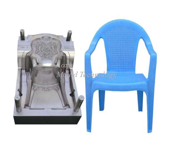
Plastic chairs are widely used due to their light weight, durability, cost-effectiveness, and ease of mass production. The key to manufacturing high-quality plastic chairs lies in the precision design of the injection mould. The mould determines the shape, surface finish, structural strength, and overall quality of the final product. Designing a plastic chair mould involves mechanical, material, and thermal considerations to ensure manufacturability, longevity, and efficiency in production.
2. Design Objectives
The main objectives in designing a plastic chair mould are:
To achieve accurate replication of the chair geometry.
To ensure uniform wall thickness and material flow.
To minimize cycle time and production cost.
To provide easy ejection and minimal warpage.
To ensure mould durability and ease of maintenance.
3. Design Requirements and Considerations
3.1 Product Analysis
Before mould design, the chair model (CAD design) must be analyzed for:
Dimensions and shape complexity – arms, ribs, slots, holes, etc.
Wall thickness – typically 2.5–3.5 mm for most plastic chairs.
Draft angles – 1°–3° for easy ejection.
Structural integrity – adequate ribbing and reinforcement.
Surface finish – textured or glossy.
3.2 Material Selection
Common materials for plastic chairs:
Polypropylene (PP): Excellent flow, toughness, and low cost.
High-Density Polyethylene (HDPE): Good impact resistance.
Glass-filled PP: Used for extra rigidity.
Mould material is usually P20 tool steel or H13, chosen for hardness, polishability, and thermal conductivity.
3.3 Type of Mould
Plastic chairs are typically produced using:
Injection moulds (most common).
Gas-assisted injection moulds (for hollow or lightweight designs).
Stack moulds (for high-volume production).
A two-plate injection mould is commonly used, though large chairs may require three-plate moulds for complex geometries.
4. Mould Design Process
4.1 Parting Line and Mould Orientation
The parting line separates the core and cavity. It is chosen to:
Simplify machining.
Facilitate ejection.
Minimize visible parting marks.
For chairs, the parting line is typically along the seat edge.
4.2 Core and Cavity Design
The core forms the inner surface of the chair (seat bottom and back).
The cavity forms the outer surface.
Both halves must be strong enough to withstand high clamping pressure.
4.3 Gating System
The gating system controls molten plastic flow into the cavity. It consists of:
Sprue
Runner
Gate
For large parts like chairs, multiple gates or a hot runner system is used to ensure uniform filling and avoid weld lines.
4.4 Cooling System
Efficient cooling is crucial to reduce cycle time and prevent warpage. Cooling channels are designed close to the mould surface (12–18 mm) with uniform distribution.
Modern methods like conformal cooling (3D printed channels) may be used for better efficiency.
4.5 Ejection System
Once the part solidifies, ejector pins or plates push it out of the mould. For chairs, stripper plates, air ejection, or hydraulic ejectors are often used due to large surface areas.
4.6 Venting
Proper venting avoids air traps and burn marks. Small vents (~0.02–0.05 mm deep) are placed near the last-to-fill areas.
5. Structural and Thermal Analysis
Finite Element Analysis (FEA) and Moldflow simulations are conducted to:
Predict filling patterns, pressure, and temperature distribution.
Identify potential defects (short shots, weld lines, sink marks).
Optimize gate locations, cooling layout, and wall thickness.
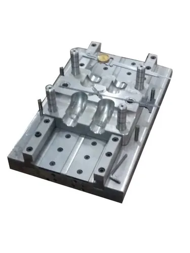
6. Manufacturing of the Mould
The mould is typically machined using:
CNC milling for rough and finish shaping.
EDM (Electrical Discharge Machining) for intricate contours.
Polishing and texturing for the final surface finish.
Heat treatment follows machining to enhance hardness and wear resistance.
7. Testing and Trial
After assembly, trial moulding runs are conducted to:
Check part quality and dimensional accuracy.
Adjust process parameters (pressure, temperature, cooling time).
Modify gate size or venting if necessary.