1. Introduction
In injection moulding, the ejection system plays a crucial role in removing the final moulded part from the cavity after it has solidified. A well-designed ejection system ensures smooth part removal without damaging the component or the mould, maintaining high productivity, part quality, and mould longevity.
2. Purpose of Ejection System
To safely and efficiently eject the moulded part from the mould cavity.
To prevent deformation or damage to the part during ejection.
To minimize cycle time by ensuring quick part removal.
To enable automation in part removal for high-volume production.
3. Design Considerations
Several factors influence the design of the ejection system:
a) Part Geometry
Complex shapes may require multiple or specialized ejectors.
Thin walls or undercuts may need stripper plates or sleeves.
b) Material Shrinkage
Materials that shrink tightly onto the core need more forceful ejection.
c) Surface Finish
Highly polished parts may stick more and require more uniform ejection.
d) Ejection Force
Calculated based on the surface area, part geometry, and material.
Must be sufficient but not excessive to avoid part damage.
e) Parting Line and Core Design
The orientation and location of the part in the mould influence the placement of ejector pins and other mechanisms.
4. Types of Ejection Systems
a) Ejector Pins
Most common method.
Small cylindrical pins push the part out.
Must be strategically located to avoid part damage and visible ejector marks.
b) Sleeve Ejectors
Hollow cylindrical ejectors used for tubular parts.
Ejects the part from around a core.
c) Stripper Plate
A plate pushes the part off the core uniformly.
Ideal for flat, large, or fragile components.
d) Air Ejection
Compressed air is used to push the part out.
Suitable for delicate or high-finish parts.
e) Blade or Plate Ejectors
Flat blades used for thin or flat parts.
Often used where ejector pins would leave visible marks.
f) Rotating or Cam-Operated Ejectors
Used for parts with undercuts or complex features.
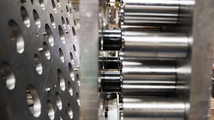
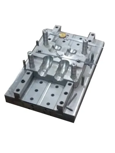
5. Ejection System Components
Ejector Pins/Sleeves
Ejector Plate and Back Plate
Return Pins
Guide Pillars and Bushes
Springs or Hydraulic Actuators (for plate or air ejection)
Stopper or Locking Mechanism (to limit ejector travel)
6. Common Problems and Solutions
| Problem | Possible Cause | Solution |
|---|---|---|
| Part sticking in cavity | Inadequate ejection force or poor surface finish | Increase number of ejectors, improve surface finish, use air ejection |
| Part warpage or breakage | Uneven ejection force | Use stripper plate or reposition ejector pins |
| Ejector marks on part | Incorrect pin location or size | Optimize pin size/location, use sleeve or blade ejectors |
| Ejector system wear | Poor alignment or lubrication | Improve alignment, use wear-resistant materials, regular maintenance |