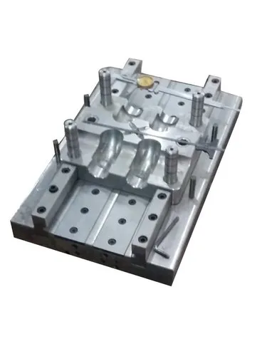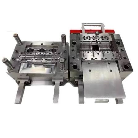
Designing an injection mould involves developing a tool that can consistently produce high-quality plastic components with accurate dimensions, efficient cycle times, and reliable mould life. A well-designed injection mould must account for the part geometry, plastic material, filling behaviour, cooling, shrinkage, ejection, and manufacturing requirements.
The mould design process generally begins with a detailed evaluation of the plastic part and continues through cavity and core design, runner and gate layout, cooling-channel design, ejection, venting, mould-base selection, and final manufacturing considerations.
1. Analyse the Plastic Part
Before starting the mould design, the component should be evaluated for:
- Overall dimensions and geometry
- Wall thickness and uniformity
- Ribs, bosses, holes, and other features
- Undercuts and difficult-to-release areas
- Required surface finish
- Dimensional tolerances
- Material type and expected shrinkage
- Production quantity and expected mould life
The part should also be designed with suitable draft angles so that it can be removed from the mould without damage.
2. Determine the Number of Cavities
The required number of cavities depends on production volume, component size, machine capacity, and required cycle time.
Common configurations include:
- Single-cavity moulds – suitable for low-volume production or large components.
- Multi-cavity moulds – produce multiple identical parts in each cycle.
- Family moulds – produce different but related components in the same cycle.
- Stack moulds – use multiple moulding levels to increase output without requiring a significantly larger machine footprint.
The cavity arrangement should provide balanced filling and efficient use of the available mould space.
3. Design the Cavity and Core
The cavity generally forms the external features of the component, while the core forms internal features.
Important considerations include:
- Parting-line location
- Wall thickness
- Draft angles
- Shrinkage allowance
- Core strength
- Ease of machining
- Surface finish
- Ejection direction
The cavity and core should be designed so that the mould opens and the part can be ejected without excessive force or deformation.
4. Select the Parting Line
The parting line is the boundary where the mould halves separate.
A properly positioned parting line should:
- Minimize visible mould marks
- Simplify mould construction
- Avoid creating unnecessary undercuts
- Support effective ejection
- Allow proper venting
- Reduce the risk of flash
The parting line should preferably be placed in an area where any resulting mould mark is acceptable.
5. Design the Runner System
The runner system carries molten plastic from the injection unit to the mould cavities.
It may include:
- Sprue
- Main runners
- Secondary runners
- Gates
For multi-cavity moulds, the runner layout should be balanced so that all cavities fill as evenly as possible. Runner dimensions should be selected according to the material, component size, flow length, pressure requirements, and expected cycle conditions.
6. Select the Gate Location and Type
The gate controls how molten plastic enters the cavity. Gate design has a major effect on filling, weld lines, shrinkage, warpage, and surface appearance.
Common gate types include:
- Edge gates
- Pin gates
- Submarine gates
- Fan gates
- Tab gates
- Hot-runner gates
The gate should generally be positioned to provide a suitable filling pattern while minimizing visible marks and undesirable weld lines.
7. Design the Cooling System
Cooling is one of the most important aspects of injection mould design because it strongly affects cycle time and part quality.
Cooling channels should be positioned to provide relatively uniform heat removal from the cavity and core.
Good cooling design helps to:
- Reduce cycle time
- Minimize warpage
- Improve dimensional stability
- Maintain consistent part quality
- Prevent localized overheating
Cooling-channel layout should consider the part geometry, wall thickness, material, mould steel, and areas that generate or retain more heat.
8. Design the Ejection System
After the plastic component has cooled sufficiently, it must be removed from the mould.
Common ejection methods include:
- Ejector pins
- Ejector sleeves
- Ejector plates
- Blade ejectors
- Air ejection
- Stripper plates
Ejectors should be positioned on structurally strong areas of the component to minimize deformation and visible ejector marks. The ejection force should also be distributed as evenly as practical.
9. Provide Proper Venting
Air trapped inside the cavity must be able to escape as molten plastic fills the mould.
Vents are commonly positioned near:
- The end of the filling path
- Weld-line areas
- Deep pockets
- Ribs
- Bosses
- Parting-line regions
Insufficient venting can cause burn marks, incomplete filling, gas traps, and poor surface quality.
10. Consider Shrinkage
Most thermoplastics shrink as they cool. The mould dimensions therefore need to account for the expected material shrinkage.
Shrinkage depends on factors such as:
- Plastic material
- Part geometry
- Processing temperature
- Mould temperature
- Packing pressure
- Cooling conditions
- Fibre reinforcement
Material-specific shrinkage data should be used during mould design rather than relying on a single universal value.
11. Select the Mould Material
Mould materials should be selected according to production volume, plastic material, surface requirements, and expected wear.
Common mould materials include:
- Pre-hardened tool steels
- Hardened tool steels
- Stainless steels
- Aluminium alloys for selected applications
High-volume production generally requires durable mould materials capable of withstanding repeated mechanical, thermal, and wear stresses.
12. Design for Manufacturing and Maintenance
The mould should not only produce the required component but also be practical to manufacture, inspect, clean, repair, and maintain.
Design considerations include:
- Standard mould components
- Replaceable inserts
- Accessible cooling channels
- Easy-to-replace wear components
- Proper alignment systems
- Adequate steel thickness
- Easy access for maintenance
- Surface treatments where required
Interchangeable inserts can be particularly useful when certain mould areas are likely to experience wear or when future design modifications are expected.
13. Verify the Mould Design
Before manufacturing the mould, the design should be checked for potential problems.
Design verification may include:
- 3D mould assembly review
- Filling analysis
- Cooling analysis
- Warpage prediction
- Ejection analysis
- Interference checking
- Mould-opening simulation
- Runner and gate evaluation
Mould-flow analysis can help identify potential issues such as short shots, weld lines, excessive injection pressure, air traps, and unbalanced filling before the tool is manufactured.
Key Factors in Injection Mould Design
A successful injection mould should provide:
- Consistent cavity filling
- Effective cooling
- Reliable ejection
- Adequate venting
- Correct shrinkage compensation
- Suitable draft angles
- Balanced runner and gate design
- Accurate cavity and core alignment
- Easy maintenance
- Long service life
- Consistent part quality
Conclusion
Injection mould design is a combination of part engineering, material knowledge, mould construction, and manufacturing considerations. The cavity and core, parting line, runner and gate system, cooling channels, venting, and ejection system must all work together to produce the component efficiently and consistently.
A properly designed injection mould reduces defects, improves cycle time, simplifies maintenance, and provides reliable long-term production performance.