1. Introduction
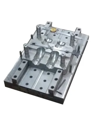
The runner system is an important part of an injection mould that carries molten plastic from the injection moulding machine nozzle to the mould cavity. It ensures that the plastic flows through the mould in a controlled manner and fills the cavity to produce the required component.
A properly designed runner system improves filling consistency, reduces material waste, minimises pressure losses, and helps maintain product quality.
Runner system design depends on several factors, including the type of plastic, component geometry, number of cavities, injection pressure, mould temperature, and production volume.
2. What Is a Runner System?
A runner system is a network of channels inside an injection mould through which molten plastic travels before entering the mould cavity.
The typical flow path is:
Injection nozzle → Sprue → Runner → Gate → Mould cavity
Each section performs a specific function:
- Sprue: Receives molten plastic from the injection machine nozzle.
- Runner: Distributes the molten plastic towards the gate or gates.
- Gate: Controls the entry of plastic into the mould cavity.
- Mould cavity: Forms the final shape of the plastic component.
In a single-cavity mould, the runner system generally supplies one cavity. In a multi-cavity mould, it distributes molten plastic to several cavities during each injection cycle.
3. Main Components of a Runner System
3.1 Sprue
The sprue is the main passage connecting the injection machine nozzle to the runner system.
Functions of the sprue:
- Receives molten plastic from the nozzle.
- Directs plastic into the runner network.
- Provides a continuous flow path during injection.
- Supports efficient transfer of molten material into the mould.
The sprue is commonly tapered to make removal easier after the plastic solidifies in a cold runner mould.
Important design considerations:
- Sprue diameter and taper.
- Compatibility with the machine nozzle.
- Pressure loss through the passage.
- Ease of sprue removal.
- Cooling and solidification behaviour.
An undersized sprue can restrict flow and increase pressure loss, while an excessively large sprue can increase material waste and cooling time.
3.2 Runner
The runner is the channel that carries molten plastic from the sprue towards the gate.
In multi-cavity moulds, runners branch into smaller channels to supply individual cavities.
Functions of the runner:
- Distributes molten plastic throughout the mould.
- Maintains adequate flow rate and pressure.
- Helps achieve consistent cavity filling.
- Supports repeatable moulding quality.
Runner dimensions must be selected according to the plastic material, flow length, injection speed, pressure requirements, and cooling behaviour.
3.3 Gate
The gate is the restricted opening between the runner and the mould cavity.
It controls how molten plastic enters the cavity and influences the filling pattern, packing behaviour, and final appearance of the component.
Functions of the gate:
- Controls the flow of molten plastic into the cavity.
- Influences cavity filling and pressure transfer.
- Affects weld-line formation and air entrapment.
- Determines the location and appearance of the gate mark.
- Influences when the cavity becomes isolated from packing pressure as the gate freezes.
Gate size and location must be chosen according to component geometry, wall thickness, material properties, and appearance requirements.
3.4 Cold-Slug Well
A cold-slug well is a small pocket provided near a runner junction or at an appropriate point in the flow path to collect cooler material at the front of the melt stream.
This cooler material may form when plastic near the nozzle or sprue loses heat between cycles.
Benefits:
- Helps prevent cooler material from entering the cavity.
- Can reduce certain surface defects.
- Helps maintain more consistent material flow.
The location and dimensions depend on the mould layout and material behaviour.
3.5 Runner Junctions
Runner junctions are points where the runner branches into two or more channels.
These junctions must be designed carefully to distribute plastic efficiently and avoid unnecessary pressure losses or stagnant regions.
Poorly designed junctions may contribute to uneven filling, excessive shear, or material degradation in certain conditions.
4. Types of Runner Systems
Runner systems are mainly classified into two categories: cold runner systems and hot runner systems.
4.1 Cold Runner System
A cold runner system uses channels that are not actively heated to keep the plastic molten. The plastic inside these channels solidifies during the moulding cycle along with the component.
After the mould opens, the moulded parts and solidified runner are removed. The runner is then separated from the parts.
Advantages
- Relatively simple mould construction.
- Generally lower initial tooling cost.
- Easier inspection and maintenance.
- Suitable for many common thermoplastic materials.
- Does not require a heated manifold system.
Disadvantages
- Produces runner scrap during each cycle.
- Can increase material consumption.
- May require additional runner separation.
- Runner cooling can increase cycle time.
- Regrinding and reuse may be restricted by material or product-quality requirements.
Applications
- General plastic components.
- Low- and medium-volume production.
- Cost-sensitive moulding applications.
- Products where runner material can be managed economically.
4.2 Hot Runner System
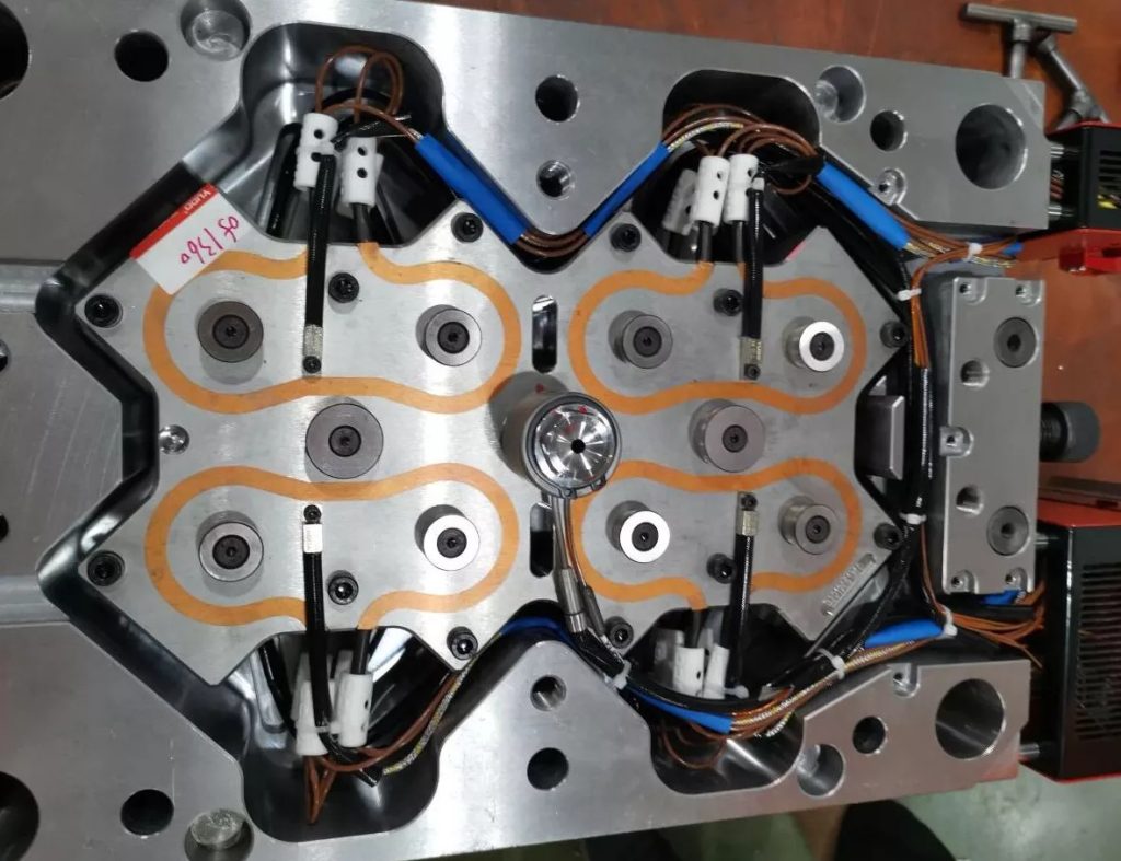
A hot runner system uses heated manifolds and nozzles to maintain the plastic in a molten state as it travels towards the cavity gates.
Because the runner material remains molten, it is generally not ejected as solid scrap during each cycle.
Main components
- Heated manifold.
- Hot runner nozzles.
- Heating elements.
- Temperature sensors.
- Temperature controller.
- Gate assemblies.
- Supporting and insulating components.
Advantages
- Greatly reduces conventional runner scrap.
- Reduces runner separation and handling.
- Can shorten the cycle by eliminating runner cooling.
- Supports automated production.
- Can improve production efficiency in suitable multi-cavity moulds.
Disadvantages
- Higher initial tooling cost.
- More complex temperature control.
- Requires specialised maintenance.
- Incorrect temperatures or long residence times can degrade sensitive materials.
- Material and colour changes may require careful purging.
Applications
- High-volume production.
- Multi-cavity moulding.
- Thin-wall packaging.
- Automotive components.
- Consumer products and precision plastic parts.
4.3 Comparison of Cold and Hot Runner Systems
| Feature | Cold runner | Hot runner |
|---|---|---|
| Runner condition | Solidifies during the cycle | Kept molten |
| Initial tooling cost | Generally lower | Generally higher |
| Runner scrap | Usually produced | Usually greatly reduced |
| Temperature control | Primarily mould cooling | Heating and cooling must be controlled |
| Maintenance | Generally simpler | More specialised |
| Cycle time | May include runner cooling | Can be shorter in suitable applications |
| Material changes | Often simpler | May require additional purging |
| Suitable production | Low to high, depending on design | Often attractive for high-volume production |
The most economical system depends on material cost, production volume, cycle time, maintenance, and the cost of the mould itself.
5. Types of Runner Cross-Sections
The cross-sectional shape of a runner affects pressure loss, heat transfer, material consumption, machining cost, and runner removal.
5.1 Full-Round Runner
A full-round runner has a circular cross-section and is commonly formed by matching semicircular channels in two mould plates.
Advantages
- Generally provides efficient melt flow.
- Has a favourable surface-area-to-volume ratio.
- Can reduce pressure loss compared with less efficient shapes of similar capacity.
Limitations
- Requires accurate machining and alignment of both mould halves.
- May increase machining complexity.
Full-round runners are widely used in conventional cold runner designs.
5.2 Trapezoidal Runner
A trapezoidal runner has a trapezoidal cross-section and can be machined into one mould plate.
Advantages
- Relatively convenient to machine.
- Can provide effective flow when properly sized.
- May simplify tooling construction.
Limitations
- Flow efficiency depends on its dimensions and corner geometry.
- May not provide the same flow characteristics as an appropriately sized full-round runner.
5.3 Half-Round Runner
A half-round runner has a semicircular cross-section and is machined into one mould half.
Advantages
- Simple machining.
- Can be useful where mould construction limits the available runner design.
Limitations
- Generally less efficient than a comparable full-round runner.
- May have higher pressure loss for a similar practical flow capacity.
5.4 Rectangular Runner
A rectangular runner has a rectangular cross-section and may be used in specialised mould designs.
Advantages
- Straightforward machining.
- Can suit certain mould layouts.
Limitations
- Sharp corners may create less favourable flow conditions.
- Material may remain in corner regions under some conditions.
- Its flow performance depends on the width-to-depth ratio and corner design.
Runner cross-section selection
For many conventional cold runner systems, a full-round runner is preferred because it offers efficient flow and good thermal characteristics. However, the final choice depends on mould construction, polymer properties, available space, and production requirements.
6. Runner Layouts in Multi-Cavity Moulds
A multi-cavity mould produces several components during one injection cycle. The runner layout must distribute molten plastic to all cavities with suitable filling and packing consistency.
6.1 Balanced Runner System
A balanced runner system is designed so that the flow resistance from the sprue to each cavity is equivalent or appropriately compensated.
In a geometrically balanced system, the cavities may have equal runner lengths, similar cross-sections, and comparable gate designs.
Advantages
- More consistent cavity filling.
- Reduced cavity-to-cavity variation.
- Improved repeatability.
- Easier process optimisation.
However, equal runner lengths do not automatically guarantee equal filling. Differences in cavity geometry, gate resistance, temperature, and polymer flow behaviour can still affect the result.
6.2 Unbalanced Runner System
An unbalanced runner system has different flow-path lengths or flow resistance between branches.
This arrangement may be required because of mould shape, component geometry, or machine constraints.
Potential disadvantages
- Unequal cavity filling times.
- Differences in cavity pressure.
- Variations in component weight.
- Uneven packing.
- Greater sensitivity to processing conditions.
Runner dimensions or gate sizes can sometimes be adjusted to compensate for these differences.
6.3 Natural Balancing
Natural balancing uses runner geometry to achieve suitable flow distribution without relying primarily on different runner sizes.
It requires careful design because identical flow-path lengths do not always result in identical filling behaviour.
6.4 Artificial Balancing
Artificial balancing adjusts runner or gate dimensions to compensate for differences in flow resistance.
For example, a branch supplying a slower-filling cavity may be modified to reduce its resistance. Such adjustments should be validated because they also affect pressure loss, shear, and packing.
7. Important Factors in Runner System Design
7.1 Runner Diameter
Runner diameter influences flow resistance, pressure loss, shear rate, cooling, and material consumption.
- An undersized runner may cause excessive pressure loss or premature freezing.
- An oversized runner may increase material consumption and cooling time in cold runner systems.
- The correct size depends on the polymer, shot volume, flow length, and required filling speed.
There is no universal runner diameter suitable for every mould.
7.2 Runner Length
Longer runners generally create greater flow resistance and pressure loss.
Where practical, runner paths should be kept compact while allowing good cavity access and suitable flow balance.
7.3 Plastic Material Viscosity
Different polymers have different flow characteristics.
High-viscosity materials may require larger passages or greater injection pressure, while lower-viscosity materials may flow more easily through narrow channels.
The design must consider how viscosity changes with temperature and shear rate.
7.4 Injection Pressure and Speed
The runner system must allow the cavity to fill within the required time without exceeding the machine’s pressure capability.
Excessive restriction can increase shear heating, while inappropriate injection speed can contribute to defects such as burn marks, flow hesitation, or poor surface quality.
7.5 Mould Temperature
Mould temperature influences how quickly the plastic cools.
In a cold runner system, premature solidification can restrict flow. In a hot runner system, manifold and nozzle temperatures must be controlled to keep the plastic within its recommended processing range.
7.6 Gate Location and Size
The gate must be positioned and sized to promote proper filling, packing, and part quality.
Poor gate design can cause:
- Weld lines.
- Visible gate marks.
- Excessive shear.
- Premature gate freezing.
- Uneven packing and shrinkage.
7.7 Venting
Air inside the cavity must escape as the molten plastic advances.
Although vents are not part of the runner channel itself, venting and runner design must be considered together. Inadequate venting can contribute to burn marks, short shots, and incomplete filling.
8. Common Runner System Problems and Solutions
| Problem | Possible cause | Recommended solution |
|---|---|---|
| Short shots | Insufficient pressure, restricted flow, or premature freezing | Check runner and gate dimensions, melt temperature, and injection settings |
| Excessive pressure loss | Long or narrow runners, abrupt transitions, or high viscosity | Optimise runner geometry and processing conditions |
| Unequal cavity filling | Unequal flow resistance or temperature variation | Review runner balance, gates, and mould temperatures |
| Flash | Excessive cavity pressure, insufficient clamping, or damaged parting surfaces | Check clamp capacity, pressure settings, and mould condition |
| Burn marks | Trapped air or excessive shear heating | Improve venting and review flow restrictions and injection speed |
| Weld lines | Flow fronts meeting around features or between separate gates | Review gate location, filling pattern, temperature, and venting |
| Excessive runner scrap | Oversized runner or unsuitable layout | Optimise runner dimensions or evaluate a hot runner system |
| Material degradation | Excessive temperature, long residence time, or stagnant regions | Adjust temperature settings and remove material-retention areas |
| Early gate freeze | Gate too small or unsuitable packing conditions | Review gate dimensions and packing parameters |
| Part-weight variation | Inconsistent filling or packing | Investigate cavity balance, gate freeze, and process stability |
9. Runner Systems in Single-Cavity and Multi-Cavity Moulds
Single-Cavity Mould
A single-cavity mould produces one component per injection cycle.
Its runner system may consist of a sprue, a short runner, and a gate, depending on the design.
Advantages
- Relatively simple flow path.
- Easier process adjustment.
- Lower tooling complexity in many applications.
Multi-Cavity Mould
A multi-cavity mould produces several components per injection cycle. Its runner system must distribute the molten plastic to all cavities.
Advantages
- Higher production output per cycle.
- Potentially lower moulding cost per component.
- Efficient production when cavity filling is well controlled.
Challenges
- More complex runner layout.
- Greater need for balanced filling.
- More demanding temperature and pressure control.
- Increased importance of consistent gate design and venting.
The runner system must also be compatible with the injection machine’s shot capacity, pressure capability, and clamping force.
10. How to Select Between Cold and Hot Runner Systems
A cold runner system may be preferable when:
- Initial tooling cost is a major consideration.
- Production volumes are relatively low or moderate.
- Runner waste can be managed economically.
- Simple maintenance is desirable.
- The material and component design suit conventional runner channels.
A hot runner system may be preferable when:
- Production volumes are high.
- Runner material is expensive.
- Automated production is required.
- Reducing runner handling is important.
- The polymer can be processed safely within the hot runner’s operating range.
The decision should be based on the total cost of ownership, including material, tooling, cycle time, maintenance, and expected production volume.
11. Best Practices for Runner System Design
1. Study the component geometry. Consider wall thickness, flow length, gate location, and areas where air may become trapped.
2. Select the runner type early. Cold and hot runner systems require different mould layouts and cost planning.
3. Aim for balanced filling. Design suitable flow paths and verify cavity filling through analysis or mould trials.
4. Avoid abrupt transitions. Smooth changes in runner direction and cross-section can reduce unnecessary pressure losses.
5. Provide cold-slug control where necessary. Prevent cooler material at the front of the melt stream from entering critical areas of the component.
6. Optimise runner dimensions. Balance pressure loss, cooling time, material use, and process stability.
7. Coordinate the runner, gate, and vents. These features jointly influence filling behaviour and component quality.
8. Use mould-flow simulation when appropriate. Simulation can help predict filling patterns, pressure requirements, weld lines, and cavity imbalance.
9. Validate the design through mould trials. Check filling, packing, part weight, and quality under actual production conditions.
10. Maintain process records. Document temperatures, injection settings, and quality measurements to improve repeatability.
12. Conclusion
The runner system is a critical element of injection mould design because it controls the movement of molten plastic from the machine nozzle to the mould cavity.
Its performance depends on the sprue, runner dimensions, gate design, cavity layout, polymer properties, temperature control, and injection parameters.
A properly designed runner system helps achieve consistent filling, lower pressure loss, reduced material waste, improved product quality, and efficient production cycles.
The best runner system is the one that provides reliable melt flow, appropriate cavity balance, consistent component quality, and economical production for the specific moulding application.