1. Introduction
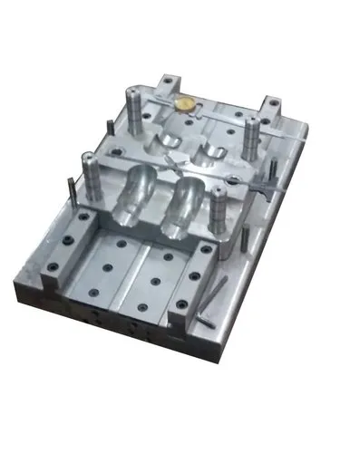
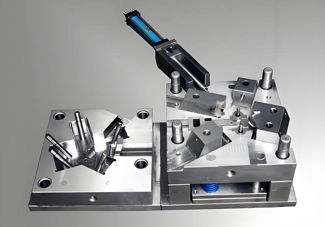
Mould parting line design is an important aspect of mould engineering that involves determining the location and geometry of the line where two or more mould sections meet or separate. This line is known as the parting line or parting surface.
The parting line allows the mould to open so that the finished component can be removed after the moulding process. Its position affects product appearance, dimensional accuracy, mould complexity, manufacturing cost, flash formation, and ease of demoulding.
Parting line design is used in various manufacturing processes, including injection moulding, compression moulding, blow moulding, die casting, and thermoforming.
2. Definition of a Parting Line
A parting line is the boundary on a moulded product where the mating surfaces of the mould sections meet during the closed moulding operation.
In a typical two-part mould, the two main sections are:
- Cavity side: Forms the external surfaces of the component.
- Core side: Forms internal surfaces, recesses, or other features, depending on the component design.
When the mould closes, the cavity and core meet along the parting surface. When the mould opens, the component is released for removal.
The parting line may appear as a fine line, a slight ridge, or a visible surface transition on the finished product.
3. Functions of Mould Parting Line Design
Proper parting line design serves several important purposes.
- Enables product removal: Allows the mould to open without trapping the component.
- Controls product quality: Helps reduce flash, mismatch, and visible surface defects.
- Simplifies mould construction: Minimises unnecessary slides, lifters, and complicated tooling arrangements.
- Improves dimensional accuracy: Helps maintain correct alignment between mould sections.
- Reduces manufacturing costs: Can simplify machining, assembly, maintenance, and production.
- Supports efficient production: Facilitates reliable mould opening, closing, and ejection.
- Improves appearance: Places unavoidable parting marks in less noticeable locations whenever possible.
4. Types of Parting Line Designs
The appropriate parting line depends on component geometry, the moulding process, tooling requirements, and product appearance.
4.1 Flat or Straight Parting Line
A flat parting line lies on a single plane and is generally the simplest arrangement.
Characteristics:
- Easy to machine and inspect.
- Straightforward mould construction.
- Good potential for consistent sealing between the mould halves.
- Usually economical to manufacture and maintain.
Applications: Simple plastic components, flat covers, basic containers, and straightforward compression-moulded parts.
Limitation: It may not be suitable for components with complex contours, undercuts, or features that cross the proposed parting plane.
4.2 Stepped Parting Line
A stepped parting line changes direction or height in distinct stages rather than remaining on one plane.
Characteristics:
- Accommodates changes in component geometry.
- Can improve mould alignment and support local sealing.
- Requires more complex machining and inspection than a simple flat parting line.
Applications: Housings, irregularly shaped components, and mouldings with different surface levels.
Limitation: Incorrectly designed steps can increase machining costs, complicate mould assembly, and create local flash risks.
4.3 Curved or Contoured Parting Line
A curved parting line follows the shape or contour of the component.
Characteristics:
- Can follow complex product geometry.
- May reduce the need for additional moving mould components.
- Requires careful three-dimensional design and machining.
Applications: Ergonomic housings, curved covers, decorative components, and complex plastic products.
Limitation: The sealing surfaces must be designed accurately to avoid gaps, mismatches, and uneven contact.
4.4 Angled Parting Line
An angled parting line is inclined relative to the principal mould opening direction or a reference plane.
Characteristics:
- Can accommodate sloped surfaces.
- May help position the parting line away from prominent product surfaces.
- Requires consideration of opening direction, draft angles, and component retention.
Applications: Sloped housings, tapered products, and mouldings with inclined geometry.
Limitation: An angled parting line does not automatically eliminate undercuts. Features that prevent straight withdrawal may still require side actions or other tooling mechanisms.
4.5 Complex or Multi-Level Parting Line
A complex parting line combines several planes, steps, curves, or other transitions. It may be necessary when a component has intricate geometry.
Characteristics:
- Accommodates complex shapes.
- Can help avoid difficult trapped geometries.
- Requires more detailed design, manufacturing, and maintenance.
Applications: Automotive components, technical housings, complex consumer products, and moulds with several interacting sections.
Limitation: Greater tooling complexity can increase cost, alignment sensitivity, and maintenance requirements.
5. Factors Affecting Parting Line Location
Selecting the parting line is a balance between product design, mould construction, and production requirements.
5.1 Component Geometry
The overall shape of the component is the primary consideration.
The parting line should ideally follow a natural boundary in the product geometry and permit the mould to open without interference.
Complex ribs, bosses, recesses, and protrusions must be assessed to determine whether they can be formed with a simple two-part mould.
5.2 Mould Opening Direction
The opening direction determines how the mould sections separate.
The designer should select a direction that allows the component to be withdrawn without damaging its surfaces or trapping it in the mould. In injection moulding, the opening direction is often selected together with the core-and-cavity arrangement and the expected direction of ejection.
5.3 Draft Angle
Draft is the slight taper provided on surfaces parallel to the direction of mould opening.
Adequate draft reduces friction and helps the component release from the mould. Insufficient draft may cause sticking, scuffing, or excessive ejection force.
The required draft depends on the material, surface texture, wall depth, geometry, and manufacturing process.
5.4 Undercuts
An undercut is a feature that prevents the moulded component from being removed directly along the primary opening direction.
Examples include:
- Side holes.
- Hook-shaped projections.
- Internal locking features.
- Recesses that capture part of the mould.
A well-selected parting line may reduce undercut problems. If an undercut cannot be eliminated through geometry or parting-line changes, the mould may require slides, lifters, collapsible cores, or other mechanisms.
5.5 Surface Appearance
The parting line can leave a visible mark on the finished component. For products with high aesthetic requirements, the line should be placed where it is less noticeable or where it coincides with a natural edge, seam, or change in surface geometry.
Examples include the underside of a container, the rear surface of a housing, or a non-decorative edge.
5.6 Flash Prevention
Flash is excess material that escapes through a gap between mould sections.
An appropriately designed parting surface, accurate machining, adequate clamping force, and proper mould maintenance help prevent flash.
The design should avoid narrow, unsupported, or difficult-to-maintain sealing regions where possible.
5.7 Material Properties
Different materials behave differently during moulding.
Material viscosity, shrinkage, flow characteristics, elasticity, processing temperature, and pressure all influence the required mould design.
For example, a material that flows readily into small gaps may require particularly careful parting-surface control.
5.8 Manufacturing and Maintenance Cost
A simple parting line is generally less expensive to machine and maintain than a complicated one.
Designers should consider:
- Tool machining time.
- Mould alignment requirements.
- Inspection and measurement.
- Wear and maintenance access.
- Expected production volume.
- Replacement of damaged or worn tooling surfaces.
A more complex parting line may be justified when it significantly improves product function or eliminates expensive moving mechanisms.
6. Design Procedure for a Parting Line
A systematic approach helps achieve a practical and reliable mould design.
Step 1: Analyse the component
Review the product drawing or 3D model. Identify wall thicknesses, ribs, bosses, holes, recesses, undercuts, cosmetic surfaces, and dimensional requirements.
Step 2: Select the opening direction
Determine the direction in which the mould halves should separate. Consider component removal, ejection, and any side actions required.
Step 3: Identify candidate parting lines
Evaluate flat, stepped, angled, curved, or multi-level alternatives. Prefer a location that follows the geometry and permits straightforward tool separation.
Step 4: Check draft and undercuts
Verify that the component can be released. Modify the parting line or opening direction where practical, and identify any unavoidable side-action requirements.
Step 5: Design the parting surfaces
Establish the mating geometry and suitable shut-off surfaces. Ensure that the mould sections can close, seal, and align reliably.
Step 6: Validate the design
Check for trapped geometry, flash risks, interference, ejection problems, manufacturing difficulty, and visible parting marks. Use CAD analysis and mould-flow simulation where appropriate.
7. Parting Line Design in Different Moulding Processes
Although the underlying principle is similar, parting-line requirements vary with the manufacturing process.
| Moulding process | Main design considerations |
|---|---|
| Injection moulding | Melt pressure, flash prevention, core-and-cavity alignment, draft, undercuts, and ejection |
| Compression moulding | Material charge placement, mould closure, flash control, and trimming requirements |
| Blow moulding | Parting marks, pinch-off regions, wall distribution, and removal of excess material |
| Thermoforming | Sheet contact, trim-line position, forming geometry, and release from the tool |
| Die casting | Metal flow, high-pressure sealing, venting, casting geometry, and flash removal |
For injection moulding, the parting line is commonly defined by the meeting of the core and cavity. In blow moulding, it may coincide with the region where the mould halves pinch and seal the softened parison. In thermoforming, the term may refer to the joint between tool sections, while the sheet’s trimming boundary is a separate design consideration.
8. Common Parting Line Design Problems and Solutions
| Problem | Likely cause | Recommended solution |
|---|---|---|
| Excessive flash | Poor mating contact, mould wear, contamination, or insufficient clamping | Inspect and clean mating surfaces, restore damaged shut-offs, and verify process conditions |
| Visible mismatch | Misalignment between mould sections or locating components | Check alignment features, guide pins, bushings, and mould seating |
| Difficult demoulding | Insufficient draft or unsuitable opening direction | Increase draft where possible, review the opening direction, and assess release mechanisms |
| Scratches near the parting line | Dragging, poor release, or sharp transitions | Improve draft, polish appropriate surfaces, and correct the ejection sequence |
| Excessive tooling cost | Unnecessarily complicated parting geometry | Simplify the parting line and reconsider component geometry |
| Parting mark on a cosmetic surface | Poorly chosen parting-line location | Relocate the line to a less visible area or a natural product edge |
| Local material leakage | Inadequate shut-off geometry or excessive pressure | Improve sealing surfaces and review the moulding process conditions |
Important: Flash and mismatch are not always caused by parting-line geometry alone. Machine settings, mould wear, material behaviour, contamination, and clamping conditions should also be investigated.
9. Best Practices for Parting Line Design
The following practices help improve mould performance and product quality.
- Keep the design as simple as practical. A simpler parting line often reduces machining, assembly, and maintenance costs.
- Avoid unnecessary moving mechanisms. Adjust the parting line or product geometry before introducing slides and lifters, where feasible.
- Provide appropriate draft. Ensure that moulded surfaces can release without excessive force or damage.
- Protect cosmetic surfaces. Place parting marks on less visible surfaces whenever product requirements permit.
- Design reliable shut-off surfaces. Ensure adequate contact and support to resist the conditions experienced during moulding.
- Account for shrinkage and tolerances. The mould must be designed around the expected behaviour of the selected material and the required finished dimensions.
- Plan for inspection and maintenance. Make important mating surfaces accessible for cleaning, measurement, and repair.
- Use CAD and simulation tools. Three-dimensional analysis can reveal undercuts, interference, difficult shut-offs, and potential manufacturing problems before tooling begins.
- Validate with trials. Mould trials help confirm part release, dimensional accuracy, flash control, and the visibility of the parting mark.
10. Parting Line Design: A Practical Example
Consider a plastic storage-container lid with a flat top, a surrounding rim, and a locking feature.
A straight parting line around the perimeter may be suitable if the rim and locking geometry permit the mould halves to separate without trapping the component.
However, if the locking feature extends inward and creates an undercut, the designer must evaluate several options:
- Modify the locking feature to allow straight withdrawal, if the functional requirements permit.
- Change the parting-line location or opening direction to accommodate the geometry.
- Introduce a slide or another suitable side-action mechanism if the undercut must remain.
The final choice depends on product function, tooling cost, production volume, and dimensional requirements. A design that is easiest to mould is not necessarily acceptable if it compromises the locking performance of the lid.
11. Quality Inspection of the Parting Line
After mould manufacture and during production, the parting line should be checked for both tooling integrity and product quality.
Key inspection points include:
- Alignment: Confirm that the core and cavity meet in their intended positions.
- Flash: Check for excess material along the joint.
- Surface finish: Inspect for scratches, burrs, dents, and uneven transitions.
- Dimensions: Measure critical features near the parting line.
- Repeatability: Confirm that the line remains consistent across production samples.
- Tool condition: Look for wear, damage, contamination, and corrosion on mating surfaces.
Inspection may involve visual examination, dimensional measurement, surface-profile assessment, and checks against the approved product drawing.
12. Conclusion
Mould parting line design is a fundamental element of mould engineering because it determines how the mould opens, how the component is formed and released, and how effectively the tooling performs in production.
A good design balances component geometry, mould opening direction, draft, undercuts, sealing, surface appearance, dimensional accuracy, manufacturing cost, and maintenance requirements.
The most effective parting line is generally the simplest practical arrangement that produces the required component reliably, minimises defects, and supports efficient mould manufacture and operation.