1. Introduction
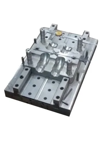
Aluminium thermoforming moulds are moulds manufactured from aluminium or aluminium alloys and used to shape heated thermoplastic sheets into specific products. Thermoforming is a manufacturing process in which a plastic sheet is heated until it becomes pliable and then formed over or into a mould using vacuum, air pressure, mechanical force, or a combination of these methods.
Aluminium is widely used for thermoforming moulds because it offers excellent thermal conductivity, relatively low weight compared with many tool steels, good machinability, and the ability to produce accurate and repeatable mould surfaces.
These moulds are commonly used to manufacture packaging trays, food containers, medical packaging, appliance liners, automotive interior components, protective housings, and other plastic products.
2. What Is an Aluminium Thermoforming Mould?
An aluminium thermoforming mould is a forming tool made primarily from aluminium alloy that provides the shape and surface characteristics of a thermoformed plastic component.
During production, a heated plastic sheet is brought into contact with the mould. Vacuum pressure, positive air pressure, or mechanical assistance forces the softened sheet to conform to the mould surface. After cooling, the plastic retains the required shape and is removed from the tool.
Depending on the application, aluminium moulds may be designed for:
- Vacuum forming.
- Pressure forming.
- Matched-mould forming.
- Plug-assisted thermoforming.
- Single-cavity or multi-cavity production.
- Prototype development or high-volume manufacturing.
The mould can be designed as a male tool, female tool, or matched set, depending on the desired component geometry and surface finish.
3. Why Aluminium Is Used for Thermoforming Moulds
Aluminium has several properties that make it suitable for thermoforming applications.
3.1 High Thermal Conductivity
Aluminium transfers heat efficiently. This helps the mould absorb heat from the formed plastic sheet and supports relatively rapid, uniform cooling.
Benefits include:
- Shorter cooling cycles in suitable applications.
- More consistent temperature distribution.
- Improved production efficiency.
- Reduced risk of localised overheating or uneven cooling when the mould is properly designed.
However, thermal conductivity alone does not guarantee uniform cooling. Cooling-channel layout, wall thickness, water flow, mould contact, and operating conditions also affect performance.
3.2 Low Weight
Aluminium is considerably lighter than many steel tooling materials.
This can make moulds easier to handle, install, remove, and maintain. Lower tool mass may also reduce the mechanical load associated with changing moulds and operating moving tooling assemblies.
3.3 Excellent Machinability
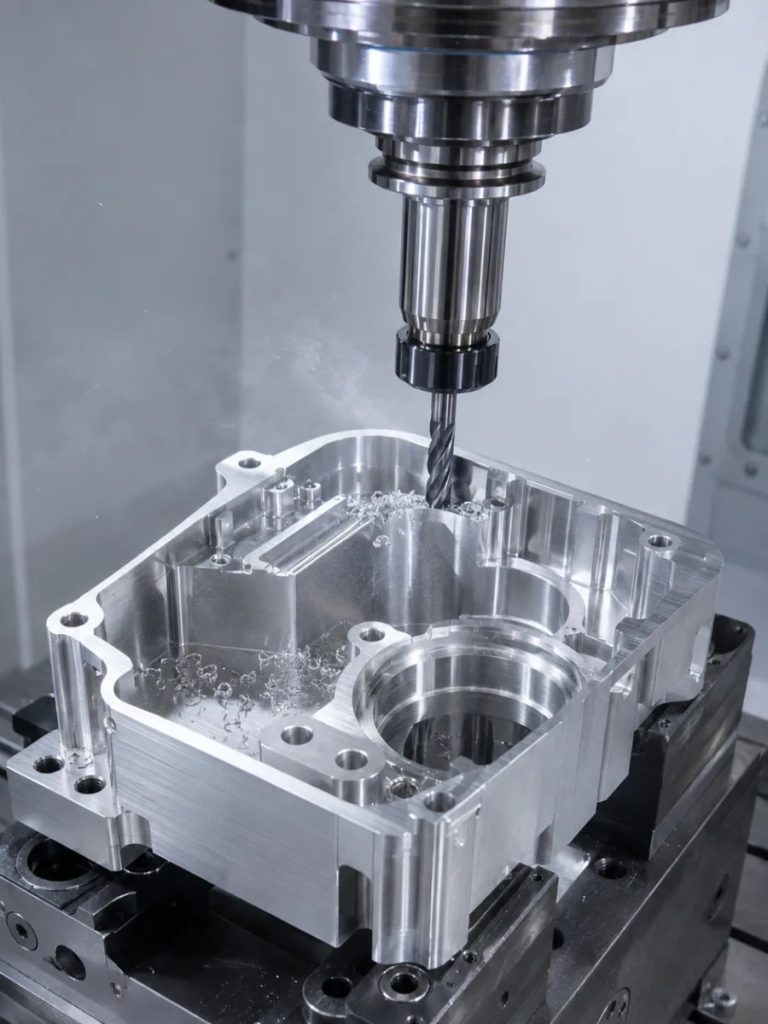
Aluminium can be machined using common CNC milling, drilling, turning, and other precision manufacturing methods.
This makes it practical to manufacture:
- Complex cavities and contours.
- Detailed surface textures.
- Vacuum holes and channels.
- Cooling passages.
- Accurate mounting features.
Good machinability can reduce tooling lead time and manufacturing costs, especially for complex mould geometries.
3.4 Good Dimensional Accuracy
Aluminium moulds can achieve accurate dimensions and repeatable geometry when appropriate machining, finishing, and temperature-control practices are used.
Dimensional stability still depends on the selected alloy, mould size, operating temperature, clamping arrangement, and design.
3.5 Corrosion Resistance
Many aluminium alloys develop a naturally protective oxide layer. This provides useful corrosion resistance in normal operating environments.
Nevertheless, certain coolants, cleaning chemicals, moisture conditions, and dissimilar-metal contacts can cause corrosion. Appropriate alloy selection, surface treatment, and maintenance remain important.
4. Common Aluminium Alloys Used in Thermoforming Moulds
Different aluminium alloys offer different combinations of strength, machinability, corrosion resistance, and thermal properties.
| Aluminium alloy | Main characteristics | Typical suitability |
|---|---|---|
| 6061 | Good machinability, strength, and corrosion resistance | General-purpose mould bases and tooling |
| 6082 | Good strength and machinability, particularly common in European engineering applications | Structural tooling and mould components |
| 7075 | High strength and good machinability, but generally lower corrosion resistance than 6061 | Applications requiring high mechanical strength |
| 5083 | Good corrosion resistance and useful properties for certain fabricated components | Selected mould structures and tooling plates |
| Cast aluminium tooling alloys | Designed for casting and subsequent machining, with properties depending on the specific grade | Large moulds and complex tool bodies |
Important: Not every aluminium alloy is suitable for every mould. Alloy selection should account for forming pressure, tool size, required finish, operating temperature, wear, and the intended production volume. Cast tooling alloys and wrought aluminium alloys may behave differently during machining and thermal cycling.
5. Types of Aluminium Thermoforming Moulds
5.1 Male or Positive Moulds
A male mould, also called a positive mould, projects outward from the mould base.
The heated plastic sheet is drawn over the mould surface.
Advantages
- Relatively straightforward construction for many shapes.
- Useful for products where the outside surface follows the tool contour.
- Can provide good control of selected internal dimensions.
Limitations
- Material may thin near corners and deep features.
- The surface contacting the mould may be on the inside of the finished product.
- Deep draws may require plug assistance or careful sheet-temperature control.
Applications: Covers, shells, liners, trays, and selected protective components.
5.2 Female or Negative Moulds
A female mould contains a cavity into which the heated plastic sheet is drawn.
Advantages
- Can provide good control of external product dimensions.
- Suitable for recesses and cavity-shaped products.
- Often useful for packaging and container production.
Limitations
- Deep cavities can cause uneven material distribution.
- Vacuum and vent placement may be more demanding.
- Some geometries may require careful draft design to support release.
Applications: Packaging trays, food containers, housings, and recessed components.
5.3 Matched Aluminium Moulds
Matched moulds use two complementary tool sections that close around the heated sheet.
They can provide greater control over geometry and surface detail than many single-sided forming arrangements.
Advantages
- Improved control of selected dimensions.
- Potential for detailed features on both sides.
- Suitable for specialised precision components.
Limitations
- Higher tooling cost.
- More complex alignment and maintenance.
- Greater sensitivity to clearances and sheet thickness.
Applications: Technical components, precision covers, and products requiring closely controlled features.
5.4 Plug-Assisted Moulds
Plug-assisted thermoforming uses a mechanical plug to help distribute the heated sheet before or during forming into the mould.
The plug is not necessarily made from aluminium. It may use a different material selected for its thermal and mechanical properties.
Advantages
- Helps improve material distribution in deep-draw products.
- Can reduce excessive thinning in selected regions.
- Supports more complex product geometry.
Applications: Deep food trays, cups, containers, and packaging components.
6. Main Components of an Aluminium Thermoforming Mould
An aluminium thermoforming mould may contain several functional components.
6.1 Mould Body
The mould body provides the primary forming geometry and supports the other mould features.
It includes the cavity or positive forming surface and must withstand the mechanical and thermal loads associated with the process.
6.2 Forming Surface
The forming surface is the area that determines the shape and surface characteristics of the plastic component.
It may be machined smooth, polished, textured, or treated to achieve the required product appearance and release characteristics.
6.3 Vacuum Holes
Vacuum holes allow air to escape from between the heated sheet and the mould surface during vacuum forming.
Their placement is important around:
- Deep recesses.
- Corners.
- Fine details.
- Narrow channels.
- Areas where air could become trapped.
Vacuum holes must be sufficiently small or appropriately designed to prevent unwanted marks on the finished plastic.
6.4 Vacuum Channels
Vacuum channels connect the forming surface to the vacuum supply.
They distribute suction across the mould and help remove air efficiently. Their size and arrangement depend on mould geometry, required forming speed, and the vacuum system’s capacity.
6.5 Cooling Channels
Cooling channels carry a cooling medium, commonly water, through or around the mould.
They help remove heat from the formed sheet and maintain a suitable mould temperature.
The channel layout should avoid large temperature differences across the tool, while preserving sufficient material thickness around the channels.
6.6 Mounting Plate and Support Structure
The mounting plate attaches the mould to the thermoforming machine.
It must provide sufficient stiffness and maintain alignment under operating loads. The design also needs to accommodate vacuum connections, cooling connections, and any required pneumatic or mechanical interfaces.
6.7 Venting Features
Venting features allow trapped air to escape from areas that cannot be adequately evacuated through the main vacuum system.
Depending on the design, venting may use small drilled holes, slots, or dedicated passages.
6.8 Trimming and Registration Features
Some thermoforming tools incorporate locating features or interfaces that help align the formed sheet with a separate trimming station.
The forming mould does not necessarily perform trimming itself. Forming and trimming may take place in separate tools or integrated tooling systems.
7. Design Considerations for Aluminium Thermoforming Moulds
Correct design is essential for product quality, efficient production, and long mould life.
7.1 Mould Geometry
The mould geometry must correspond to the finished component and the forming process.
Designers should consider:
- Overall dimensions.
- Draw depth.
- Corner radii.
- Wall angles.
- Local recesses and projections.
- Sheet thickness and expected material distribution.
- Mould opening and product removal.
Deep cavities and sharp corners deserve particular attention because they can produce excessive local thinning.
7.2 Draft Angle
Draft is the taper applied to surfaces in the direction of part removal.
Adequate draft reduces friction and helps the formed component release from the mould.
The required angle depends on factors such as:
- Component depth.
- Material type.
- Surface texture.
- Shrinkage.
- Mould geometry.
- Product flexibility.
A deeper or textured surface may require more draft than a shallow, smooth surface. There is no single draft angle that is correct for every thermoforming mould.
7.3 Corner Radii
Sharp corners can cause the heated sheet to stretch excessively and become thin.
Using appropriate radii helps the sheet flow over the forming surface more evenly and reduces the likelihood of tearing or weak areas.
Both internal and external transitions should be evaluated according to the geometry of the tool and the final component.
7.4 Vacuum Hole Design
Vacuum holes should be placed where air evacuation is necessary without leaving objectionable marks on the finished product.
The designer must consider:
- Hole diameter.
- Hole spacing.
- Hole depth.
- Connection to the vacuum channels.
- Surface finish requirements.
- Risk of plastic being pulled into the holes.
Hole size and spacing should be validated through forming trials where appearance or fine details are critical.
7.5 Cooling System Design
The cooling system must remove heat efficiently without producing large temperature differences across the forming surface.
Design considerations include:
- Channel diameter and spacing.
- Distance between channels and the forming surface.
- Cooling-medium flow rate.
- Inlet and outlet locations.
- Pressure drop.
- Leak prevention.
- Access for cleaning and maintenance.
Poor cooling design can result in uneven cycle times, inconsistent shrinkage, warpage, and dimensional variation.
7.6 Surface Finish
The required surface finish depends on the intended appearance and function of the final product.
A smooth mould surface may be appropriate for glossy products, while a controlled texture may be required for appearance, grip, or reduced visible surface imperfections.
Surface treatments and coatings should be selected carefully because they may influence heat transfer, wear, corrosion resistance, and product release.
7.7 Thermal Expansion
Aluminium expands as its temperature rises. This expansion can affect tool dimensions, alignment, and clearances, particularly in large moulds or applications with substantial temperature changes.
Designers should consider:
- Operating temperature.
- Mould dimensions.
- Temperature distribution.
- Mounting constraints.
- Differences in thermal expansion between adjoining materials.
7.8 Mould Stiffness
The mould must be sufficiently rigid to resist deformation under forming pressure, mounting loads, and clamping forces.
A mould that is too flexible may produce dimensional variation or inconsistent product thickness. Reinforcement, suitable wall thicknesses, and a properly designed support structure can help prevent these issues.
8. Manufacturing Process for Aluminium Thermoforming Moulds
The production of an aluminium thermoforming mould generally involves the following stages.
- Design and CAD modellingThe product geometry is evaluated and a three-dimensional mould model is prepared. Draft, vacuum routing, cooling channels, mounting interfaces, and part-removal requirements are incorporated.
- Alloy selection and material preparationAn appropriate aluminium plate, billet, or casting is selected based on mechanical, thermal, and manufacturing requirements.
- Rough machiningExcess material is removed to establish the general shape of the mould body and forming surface.
- CNC precision machiningThe cavity or positive surface is machined to the required dimensions. Mounting holes, vacuum passages, cooling channels, and other features are produced as specified.
- Finishing and deburringSharp edges and unwanted machining marks are removed. The forming surface is polished, textured, or otherwise finished according to product requirements.
- Cleaning and inspectionMachined passages are cleaned, critical dimensions are checked, and the mould is inspected for surface defects and manufacturing errors.
- System testingVacuum integrity and cooling-channel integrity are checked as applicable. Connections, mounting features, and alignment are verified.
- Trial forming and adjustmentSample components are formed to evaluate dimensional accuracy, surface quality, material distribution, release, and cycle time. Adjustments are made where necessary.
9. Advantages and Limitations of Aluminium Thermoforming Moulds
| Advantages | Limitations |
|---|---|
| High thermal conductivity | Lower hardness and wear resistance than many tool steels |
| Relatively low weight | Can be damaged by improper handling or aggressive cleaning |
| Good machinability | Large tools may require careful control of thermal expansion |
| Suitable for detailed CNC machining | Some surface treatments add cost and process complexity |
| Efficient heat transfer | Cooling performance still depends on channel design |
| Good corrosion resistance for many environments | Susceptible to corrosion under unsuitable chemical or coolant conditions |
| Can offer economical tooling production | May be less suitable for severe wear or unusually demanding service conditions |
Aluminium is often a strong choice when heat transfer, machining speed, and manageable tool weight are important. Steel or other tooling materials may be preferable where very high wear resistance, exceptional stiffness, or specialised service conditions dominate.
10. Common Problems and Troubleshooting
| Problem | Possible cause | Recommended solution |
|---|---|---|
| Uneven wall thickness | Excessive stretching, unsuitable geometry, or poor sheet-temperature distribution | Adjust forming conditions, increase corner radii, or use plug assistance |
| Incomplete forming | Insufficient vacuum, trapped air, or inadequate sheet heating | Check vacuum supply, improve venting, and optimise heating |
| Warped components | Uneven cooling or non-uniform material distribution | Improve cooling balance and review the forming cycle |
| Difficult part removal | Insufficient draft, unsuitable geometry, or excessive shrinkage around the tool | Increase draft where possible and review mould temperature and geometry |
| Visible vacuum-hole marks | Holes too large or poorly positioned | Reduce hole size, modify spacing, or adjust vent design |
| Surface scratches | Rough tool finish, contamination, or improper handling | Clean and refinish the surface and improve handling procedures |
| Long cycle time | Inadequate cooling, excessive sheet heating, or inefficient process settings | Optimise cooling flow and temperature, then adjust the heating cycle |
| Dimensional inconsistency | Temperature variation, mould movement, or inconsistent forming conditions | Check tool temperature, mounting stiffness, and process repeatability |
| Corrosion or surface deterioration | Incompatible coolant, cleaning chemicals, or environmental exposure | Use compatible fluids and cleaning methods; consider an appropriate protective treatment |
Troubleshooting should distinguish mould-design problems from heating, vacuum, material, and machine-setting problems. Changing the mould alone may not resolve a defect caused by an unstable process.
11. Aluminium Moulds Compared with Steel Moulds
| Property | Aluminium moulds | Steel moulds |
|---|---|---|
| Thermal conductivity | Generally high | Generally lower, depending on the steel grade |
| Weight | Lower | Higher |
| Machinability | Generally easier | Often requires more machining effort |
| Tooling lead time | Often shorter | Can be longer for comparable complex features |
| Wear resistance | Generally lower | Generally higher, depending on grade and treatment |
| Thermal response | Often faster | Often slower |
| Typical selection priorities | Heat transfer, weight, and machining efficiency | Wear resistance, stiffness, and demanding service conditions |
The correct choice depends on production volume, forming temperature, pressure, tool geometry, required surface finish, and maintenance expectations. Aluminium is not automatically cheaper over the full service life, just as steel is not automatically the better option for every high-volume application.
12. Maintenance of Aluminium Thermoforming Moulds
Regular maintenance preserves the forming surface and helps maintain consistent product quality.
Recommended practices include:
- Clean the forming surface using compatible materials and cleaning agents.
- Inspect vacuum holes and channels for blockages.
- Check cooling passages and connections for leaks or deposits.
- Inspect the tool for dents, scratches, corrosion, and worn surfaces.
- Verify mounting bolts, alignment features, and support structures.
- Avoid steel tools or abrasive cleaning methods that could damage the aluminium surface.
- Inspect protective coatings or surface treatments where applicable.
- Store the mould in a clean, dry environment when not in use.
- Record maintenance, repairs, and process adjustments to track recurring defects.
Before carrying out maintenance, isolate the relevant machine systems and follow the equipment manufacturer’s safety procedures.