1. Introduction
The cooling system in a mould base is a critical component that directly affects the productivity, quality, and cycle time of injection moulding processes. Its main function is to extract heat from the molten plastic after it has been injected into the mould cavity, allowing it to solidify quickly and uniformly.
2. Objectives of Cooling System Design
To reduce cycle time by accelerating cooling.
To ensure uniform cooling for dimensional stability.
To avoid defects like warping, sink marks, and residual stresses.
To improve surface finish and part quality.
To enhance mould life by minimizing thermal stress.
3. Types of Cooling Systems
a. Conventional Cooling
Straight drilled channels in mould plates.
Relatively easy to manufacture.
Limited in terms of reaching complex or deep cavities.
b. Baffle and Bubblers
Used for deep cores and small diameter areas.
Baffles split water flow to maximize heat transfer.
Bubblers are small diameter tubes inserted in drilled holes to circulate water effectively.
c. Spiral and Conformal Cooling
Spiral Cooling: Circular channels designed to spiral around the part contour.
Conformal Cooling: Follows the 3D geometry of the part, achievable using additive manufacturing (3D printing).
Offers better thermal control but higher cost.
4. Cooling Channel Design Considerations
a. Channel Diameter
Typical range: 8–12 mm.
Larger channels increase flow rate but reduce velocity and turbulence.
b. Channel Placement
Ideal distance from the mould surface: 1.5 to 2 times the diameter of the cooling channel.
Should not be too close to avoid surface defects, nor too far to reduce cooling efficiency.
c. Spacing Between Channels
Typically 3 to 5 times the diameter of the cooling channels.
Ensures uniform temperature distribution.
d. Flow Rate and Velocity
Recommended water velocity: 1.5 to 2 m/s.
Ensures turbulent flow for better heat transfer.
e. Material Selection
Mould materials with high thermal conductivity (e.g., copper alloys) enhance cooling performance.
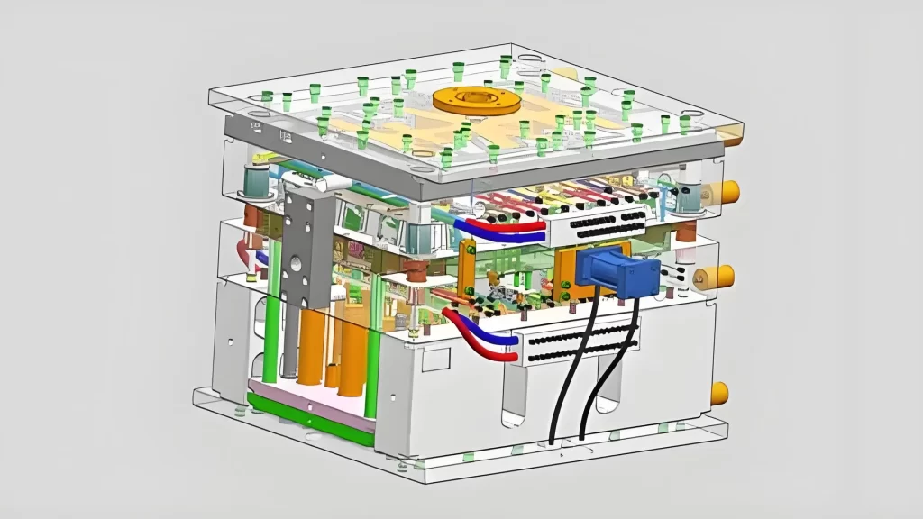
5. Cooling System Components
Inlet and Outlet Fittings: For water circulation.
Seals and O-rings: Prevent leaks in high-pressure conditions.
Flow Regulators: Control water flow rate.
Temperature Sensors: Monitor cooling efficiency and stability.
6. Cooling Analysis and Simulation
Modern software tools (e.g., Moldflow, Moldex3D) are used to:
Simulate cooling performance.
Identify hot spots and uneven temperature zones.
Optimize channel layout before manufacturing.
7. Maintenance and Troubleshooting
Routine Cleaning: To prevent scaling and clogging.
Leak Detection: Regular checks for wear or seal failure.
Flow Monitoring: Ensure consistent cooling over time.
8. Advancements and Trends
3D Printed Conformal Cooling: Revolutionizing complex moulds.
Smart Cooling Systems: Integration with sensors and IoT for real-time feedback.
Eco-friendly Coolants: Use of glycol blends or closed-loop systems.
9. Conclusion
A well-designed cooling system is vital for efficient moulding operations. Proper placement, sizing, and type of cooling channels not only improve product quality but also reduce production costs and increase mould life. As manufacturing technology advances, more sophisticated and efficient cooling solutions continue to evolve.