1. Introduction
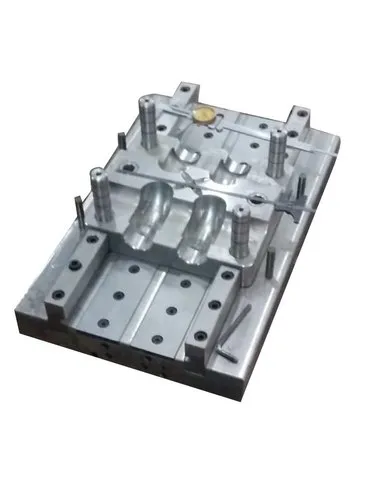
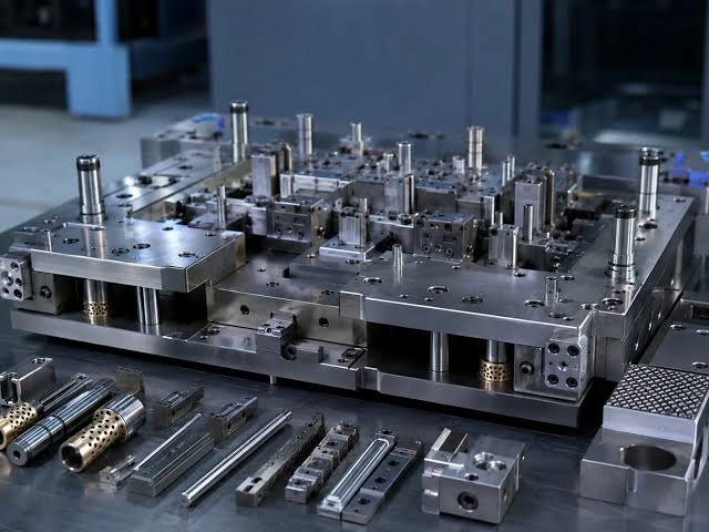
An ejection system in an injection mould is a mechanical arrangement used to remove a solidified plastic component from the mould after the injection moulding process. Once molten plastic is injected into the mould cavity, it is cooled until it becomes sufficiently rigid. The mould then opens, and the ejection system removes the finished component from the core or cavity.
The ejection system is an essential part of mould design because it directly affects product quality, production cycle time, mould reliability, and manufacturing efficiency.
In most conventional injection moulds, the ejection system is located on the moving half of the mould, commonly called the core side, because the moulded component usually shrinks around and remains attached to the core during mould opening.
2. Functions of an Ejection System
The main functions of an ejection system are:
- To remove the moulded component from the mould after cooling.
- To overcome friction, shrinkage grip, and adhesion between the component and the mould surface.
- To prevent damage, cracking, bending, or deformation during removal.
- To minimize ejector marks and other surface defects.
- To ensure consistent and repeatable ejection during mass production.
- To reduce the overall moulding cycle time.
- To return the ejector mechanism to its original position before the next injection cycle.
3. Main Components of an Ejection System
3.1 Ejector Pins
Ejector pins are cylindrical steel pins used to push the moulded component away from the core.
- They are the most commonly used ejection elements.
- They are positioned at suitable locations on the moulded component.
- They must withstand repeated mechanical loads.
- They are manufactured from suitable tool steels to provide strength and wear resistance.
Applications: Plastic housings, containers, automotive components, and general-purpose moulded products.
3.2 Ejector Plate
The ejector plate supports the ejector pins and transfers movement from the machine’s ejection mechanism to the pins.
When the ejector mechanism advances, the plate moves forward and pushes the pins against the moulded component.
3.3 Ejector Retainer Plate
The ejector retainer plate holds the ejector pins in their correct positions. It is generally fastened to the ejector plate and prevents the pins from becoming displaced during repeated operation.
3.4 Return Pins
Return pins help bring the ejector assembly back to its initial position when the mould closes. Depending on the mould design, the return movement may also use springs or a machine-driven return mechanism.
3.5 Guide Pins and Guide Bushes
These components guide the movement of the ejector plates and help maintain alignment. Proper guidance reduces friction, uneven wear, and the risk of jamming.
3.6 Stop Pins
Stop pins limit or establish the final position of the ejector assembly. They help prevent unwanted contact between the ejector plates and other mould components.
3.7 Support Pillars
Support pillars provide structural support to the mould and help prevent excessive bending of the plates under operating loads.
4. Working Principle of an Ejection System
The operation of an ejection system follows a sequence of steps.
Step 1: Injection and filling
Molten plastic is injected into the mould cavity under pressure. The plastic fills the cavity and takes the required shape.
Step 2: Cooling and solidification
The plastic cools inside the mould until it has sufficient rigidity to withstand the ejection force.
Step 3: Mould opening
The moving half of the mould separates from the fixed half. The moulded component generally remains on the core side due to shrinkage and the geometry of the component.
Step 4: Ejector movement
The injection moulding machine’s ejector rod or another actuation mechanism moves the ejector plate forward.
Step 5: Component ejection
The ejector pins, sleeves, stripper plate, or other ejection elements apply force to release the component from the core.
Step 6: Ejector return
The ejector assembly returns to its original position. The mould closes, and the next injection cycle begins.
5. Types of Ejection Systems in Injection Moulds
Different ejection systems are selected according to component geometry, material properties, surface finish requirements, and production conditions.
5.1 Ejector Pin System
The ejector pin system uses cylindrical pins to push the component away from the core.
Working principle: When the ejector plate advances, the pins move forward and apply force to the moulded component at selected contact points.
Advantages:
- Simple and economical construction.
- Easy to manufacture and maintain.
- Suitable for a wide range of moulded components.
- Pins can be positioned at multiple locations.
Disadvantages:
- May leave circular marks on the component.
- Concentrated forces can cause dents or deformation.
- Requires careful pin positioning.
Applications: Plastic covers, housings, electrical components, and general engineering parts.
5.2 Ejector Sleeve System
An ejector sleeve is a hollow cylindrical component that moves around a core pin to release a moulded part.
Working principle: The sleeve advances around the core pin and pushes against a circular region of the component.
Advantages:
- Distributes ejection force around a circular area.
- Reduces localized stress compared with a single small pin.
- Suitable for components with cylindrical bosses.
Disadvantages:
- Requires precise alignment and machining.
- May increase mould manufacturing costs.
- Can be unsuitable for irregular component geometry.
Applications: Plastic bosses, cylindrical parts, circular projections, and components with holes.
5.3 Stripper Plate System
A stripper plate is a plate-shaped mechanism that pushes the moulded component away from the core over a relatively large contact area.
Working principle: After the mould opens, the stripper plate moves forward and separates the component from the core.
Advantages:
- Distributes ejection force over a larger area.
- Reduces concentrated stress and visible pin marks.
- Suitable for thin-walled and cylindrical components.
Disadvantages:
- More complex mould construction.
- Higher manufacturing and maintenance costs.
- Requires accurate alignment and suitable clearances.
Applications: Cups, bottle caps, containers, thin-walled cylindrical products, and components requiring a clean external surface.
5.4 Blade Ejector System
Blade ejectors are thin, rectangular ejector elements used where ordinary round pins cannot fit or provide sufficient contact.
Working principle: The blade advances against a narrow section of the moulded component and pushes it away from the core.
Advantages:
- Suitable for narrow spaces.
- Effective for ejecting thin ribs and rectangular features.
- Provides localized support in restricted areas.
Disadvantages:
- Thin blades may bend or break under excessive load.
- Require careful manufacturing and alignment.
- May create visible marks on the component.
Applications: Thin ribs, narrow walls, rectangular slots, and slender moulded features.
5.5 Air Ejection System
An air ejection system uses compressed air to help separate the component from the mould surface.
Working principle: Air is introduced through an appropriately designed valve or port to break the seal between the moulded component and the core.
Advantages:
- Can help overcome vacuum-related sticking.
- May reduce the need for additional ejector pins.
- Useful for large components with extensive core contact.
Disadvantages:
- Requires a controlled compressed-air supply.
- Needs suitable air passages and venting.
- May not provide sufficient force as the sole ejection method for every component.
Applications: Deep containers, large thin-walled products, and components that tend to stick to broad core surfaces.
5.6 Lifter System
A lifter is a moving mould component used to release internal or side undercuts during ejection.
Working principle: As the ejector assembly moves forward, the lifter travels along an inclined path, moving outward or sideways to disengage the undercut.
Advantages:
- Allows moulding of components with complex internal features.
- Can eliminate the need for some separate side-action mechanisms.
- Supports automated demoulding.
Disadvantages:
- Requires accurate sliding and angular movement.
- Can experience wear at contact surfaces.
- Increases mould design complexity.
Applications: Plastic housings, clips, internal hooks, and components with undercut features.
5.7 Collapsible Core System
A collapsible core is a specialized core mechanism that contracts to release internal undercuts.
Working principle: After moulding, the core segments or collapsing mechanism retract inward, reducing the core’s effective diameter so that the component can be removed.
Advantages:
- Allows production of components with difficult internal geometries.
- Can release certain internally threaded or undercut parts.
- Supports automated high-volume production.
Disadvantages:
- High initial cost.
- Complex construction and maintenance.
- Requires precise design and operating control.
Applications: Special closures, internally undercut components, and certain threaded plastic parts.
Note: Some internally threaded components are better produced using unscrewing mechanisms rather than collapsible cores. The correct choice depends on the thread and component geometry.
5.8 Robotic or Mechanical Take-Out System
A robotic or mechanical take-out system removes the moulded component using a gripper or handling mechanism after the mould opens. It is commonly used alongside a conventional mould ejection system.
Advantages:
- Reduces manual handling.
- Improves production consistency.
- Supports automated manufacturing.
- Can reduce handling damage.
Disadvantages:
- Requires additional equipment and integration.
- Increases initial investment.
- Needs appropriate programming, maintenance, and safety controls.
Applications: High-volume manufacturing, precision moulding, and automated production lines.
6. Comparison of Ejection Systems
| Type | Suitable application | Main advantage |
|---|---|---|
| Ejector pin | General plastic components | Simple and economical |
| Ejector sleeve | Circular bosses and projections | Distributed circular force |
| Stripper plate | Cups and thin-walled parts | Uniform force distribution |
| Blade ejector | Thin ribs and narrow features | Fits restricted spaces |
| Air ejection | Large or deep components | Helps break surface adhesion |
| Lifter | Internal or side undercuts | Releases complex geometry |
| Collapsible core | Internal undercuts | Enables specialized demoulding |
| Robotic take-out | Automated production | Consistent part handling |
7. Design Considerations for Ejection Systems
A properly designed ejection system must consider the following factors.
7.1 Ejector Pin Position
Ejector pins should be placed in structurally strong regions of the component, such as suitable ribs, bosses, or thicker sections. The layout should distribute the ejection load without damaging the product.
7.2 Ejection Force
The required force depends on shrinkage around the core, friction, surface contact, component geometry, material properties, and any vacuum effects.
Excessive force can cause cracking, dents, stress marks, or deformation.
7.3 Number and Diameter of Ejector Pins
The number and diameter of pins depend on the size, stiffness, thickness, and geometry of the component. They also depend on the strength of the pins and the permissible pressure on the plastic surface.
7.4 Draft Angle
A draft angle is a slight taper provided on moulded walls to make removal easier.
Insufficient draft increases friction and may cause sticking, scratches, or scuffing during ejection.
7.5 Surface Finish
The surface finish of the mould affects the resistance encountered during removal. A suitable finish can improve release, although textured surfaces may require additional draft or a specialized ejection arrangement.
7.6 Material Properties
Different plastics behave differently during cooling and ejection. Shrinkage, stiffness, flexibility, temperature, and wall thickness all influence the required ejection force.
7.7 Ejection Stroke
The ejection stroke must be sufficient to release the component completely. The movement must also remain within the design limits of the mould and machine.
7.8 Cooling Time
The component must be sufficiently rigid before ejection. Premature removal can cause bending, surface dents, or permanent deformation.
8. Common Problems and Their Solutions
| Problem | Possible cause | Recommended solution |
|---|---|---|
| Component sticks to the core | Insufficient draft or excessive shrinkage grip | Review draft, surface finish, and ejection layout |
| Ejector marks | Excessive local pressure or poor pin placement | Redistribute pins or adjust their dimensions |
| Component deformation | Insufficient cooling or inadequate support | Optimize cooling time and ejector placement |
| Broken ejector pins | Excessive loading, wear, or misalignment | Check pin strength, alignment, and support |
| Uneven ejection | Poor load distribution or plate misalignment | Balance the layout and improve guidance |
| Ejector plate jamming | Contamination, wear, or misalignment | Clean and inspect the mechanism |
| Incomplete ejection | Insufficient stroke or excessive sticking force | Check the stroke and investigate the cause of sticking |
| Scratches on the component | High friction or unsuitable release conditions | Review draft, surface texture, and ejection timing |
9. Maintenance of Ejection Systems
Regular maintenance is necessary to ensure reliable operation and extend mould life.
- Inspect ejector pins and sleeves for bending, wear, and breakage.
- Check ejector plates for smooth movement and proper alignment.
- Clean guide pins, guide bushes, and sliding surfaces.
- Apply suitable lubricant according to the mould manufacturer’s recommendations.
- Inspect return pins, springs, and return mechanisms.
- Remove plastic deposits and other contaminants.
- Check the ejector stroke and confirm that the assembly returns fully.
- Investigate recurring sticking, pin marks, or abnormal operating noise.
- Verify that the ejection mechanism cannot interfere with mould closure.
Maintenance should be performed using the appropriate machine shutdown and isolation procedures.
10. Example: Ejection System for a Plastic Bottle Cap
Consider a plastic bottle cap produced by injection moulding. The component may have a cylindrical outer wall, internal threads, and a sealing feature.
A suitable mould may contain:
- A core that forms the internal surface of the cap.
- A cavity that forms the external surface.
- A stripper plate or another suitable mechanism for removing the cap.
- An unscrewing mechanism or collapsible core if required by the thread geometry.
- A return mechanism that resets the ejector assembly.
After the plastic cools, the mould opens. If the cap has a thread that prevents straight removal, the thread-release mechanism first disengages it from the core. The stripping mechanism then releases the cap, which is removed manually or by automation. The mould returns to its initial position for the next cycle.
The precise arrangement depends on the cap design, plastic material, thread geometry, and production requirements.
11. Advantages of a Well-Designed Ejection System
A properly designed ejection system provides several benefits:
- Improves the quality and dimensional consistency of moulded components.
- Reduces component damage and rejection rates.
- Supports shorter and more consistent production cycles.
- Minimizes sticking and manual intervention.
- Reduces wear caused by misalignment or excessive loads.
- Improves the reliability and service life of the mould.
- Enables efficient automated production.
12. Conclusion
An ejection system is a critical mechanism in injection moulding that removes the solidified plastic component from the mould safely and efficiently.
The ejector pin system is the most common solution for general-purpose components, while ejector sleeves, stripper plates, blade ejectors, air ejection, lifters, and collapsible cores are used for specific component geometries and release requirements.
The selection of an appropriate system depends on component shape, material properties, surface finish, production volume, and mould complexity.
The main objective of ejection system design is to apply sufficient and evenly distributed force to release the component while minimizing deformation, surface defects, cycle time, and mould wear.