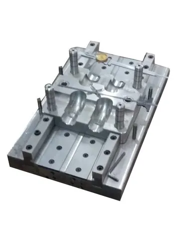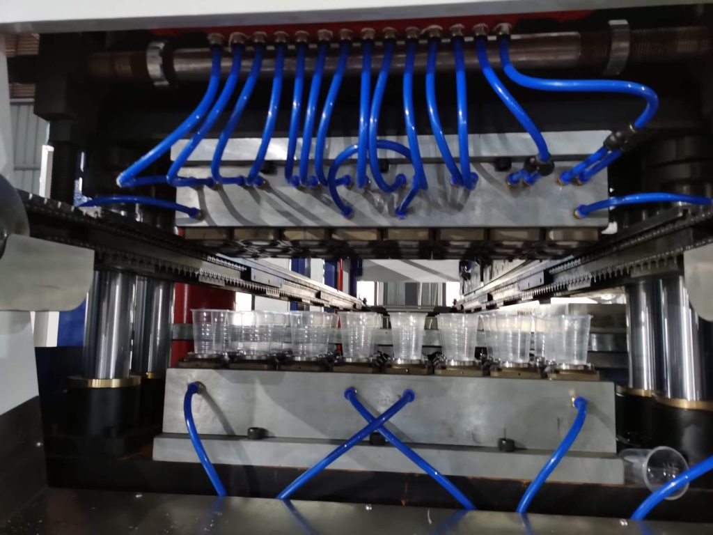
Designing a thermoforming mould is an important step in producing accurate, consistent, and high-quality plastic parts. A well-designed mould ensures that the heated plastic sheet forms correctly, releases easily, maintains uniform wall thickness, and produces the desired shape with minimal defects.
Thermoforming mould design involves considering the product geometry, plastic material, sheet thickness, forming method, draft angles, vacuum or pressure requirements, cooling, ventilation, and mould material.
1. Understand the Product Requirements
Before designing the mould, clearly define the requirements of the final thermoformed product.
Consider:
- Overall product dimensions
- Required shape and depth
- Sheet material
- Sheet thickness
- Surface finish
- Required production quantity
- Dimensional tolerances
- Strength and rigidity requirements
- Whether the product will be food-grade, industrial, medical, packaging, or decorative
- Whether trimming will be required after forming
The mould should be designed around the finished product rather than simply creating a cavity with the desired external shape.
2. Select the Thermoforming Method
The mould design depends on the thermoforming process being used.
Common methods include:
Vacuum Thermoforming
Vacuum forming uses vacuum pressure to pull the heated plastic sheet against the mould surface.
The mould needs properly positioned vacuum holes so that air can escape from between the plastic sheet and the mould.
Pressure Thermoforming
Pressure forming uses compressed air in addition to vacuum. It can produce more detailed shapes and sharper surface features.
The mould must be capable of handling the additional pressure without deformation.
Twin-Sheet Thermoforming
Twin-sheet forming uses two heated plastic sheets that are formed separately and then joined together.
Mould design must account for alignment, joining areas, internal cavities, and cooling.
3. Decide Between Male and Female Moulds
Thermoforming moulds are generally classified as male or female moulds.
Male Mould
A male mould, also called a positive mould, has a raised shape. The heated sheet is formed over the outside of the mould.
Male moulds can be useful when the inside dimensions of the product are particularly important.
Female Mould
A female mould, also called a negative mould, contains a cavity into which the heated sheet is formed.
Female moulds are commonly used when the external dimensions and surface appearance of the product are important.
The choice should be based on the required dimensions, surface finish, wall thickness distribution, and forming characteristics.
4. Consider Draft Angles
Draft angle is essential for removing the formed plastic part from the mould.
Vertical or nearly vertical mould walls can make demoulding difficult. Adding a suitable draft angle allows the finished product to release more easily.
The required draft depends on:
- Part geometry
- Material
- Surface texture
- Depth of draw
- Mould type
- Shrinkage
- Whether mechanical assistance is used
Textured surfaces generally require more draft than smooth surfaces because the plastic can grip the mould.
5. Calculate the Depth of Draw
The depth of draw describes how far the plastic sheet must stretch into or over the mould.
A deep product requires greater stretching of the plastic sheet. Excessive stretching can produce thin areas, uneven wall thickness, wrinkles, or weak sections.
During design, consider:
- Part depth
- Opening dimensions
- Shape complexity
- Material stretch characteristics
- Initial sheet thickness
- Areas requiring greater strength
For deep-draw components, pre-stretching techniques such as plug assistance may be required.
6. Account for Material Stretching
Unlike injection moulding, thermoforming starts with a relatively flat plastic sheet that must stretch over the mould.
The material does not necessarily remain at its original thickness throughout the finished component.
Corners, deep sections, and areas with significant stretching can become thinner.
Therefore, mould geometry should be designed to promote reasonably uniform material distribution.
Sharp transitions should generally be avoided where possible because they can concentrate stretching in a small area.
7. Design Proper Radii
Sharp corners are difficult to form accurately and can cause excessive material stretching.
Use suitable radii on:
- Internal corners
- External corners
- Base transitions
- Side walls
- Product edges
- Changes in depth
Larger radii generally help the heated sheet flow and stretch more smoothly around the mould.
The appropriate radius depends on the material, sheet thickness, product geometry, and forming process.
8. Add Vacuum and Vent Holes
In vacuum thermoforming, trapped air must be removed from between the plastic sheet and mould surface.
Small vent holes are therefore incorporated into the mould.
Vent holes should be positioned at locations where air is likely to become trapped, such as:
- Deep cavities
- Corners
- Recesses
- Detailed features
- Areas farthest from the primary vacuum connection
The holes should be small enough to minimize visible marks on the finished product while still allowing effective air evacuation.
Vent design is particularly important for detailed or deep components.
9. Design the Vacuum System
The mould should include an effective path for air to travel from the mould surface to the vacuum connection.
Depending on the mould design, this can involve:
- Vacuum channels
- Internal passages
- Drillings
- Connecting galleries
- Vacuum ports
The vacuum system should provide consistent suction across the mould rather than concentrating the vacuum in only one area.
Poor vacuum distribution can result in incomplete forming, trapped air, wrinkles, or inconsistent surface reproduction.
10. Consider Mould Material
Thermoforming moulds can be manufactured from different materials depending on production requirements.
Common choices include:
- Aluminium
- Epoxy tooling materials
- Tooling boards
- High-temperature plastics
- Composite materials
- Steel for specialized applications
Aluminium Moulds
Aluminium moulds are widely used for production applications because they provide good thermal conductivity, durability, and dimensional stability.
Epoxy and Composite Moulds
These can be useful for prototypes, short production runs, and applications where lower tooling costs are important.
Tooling Boards
Tooling boards can be suitable for prototypes and low-volume applications, depending on the forming temperature and material being processed.
The mould material should withstand the required forming temperature and repeated thermal cycling.
11. Plan Cooling
Cooling is an important part of thermoforming mould design.
After forming, the plastic must cool sufficiently to retain the desired shape before the component is removed.
Production moulds may incorporate cooling channels to improve cooling speed and temperature uniformity.
An effective cooling system can help:
- Reduce cycle time
- Improve dimensional stability
- Reduce deformation
- Improve repeatability
- Prevent excessive shrinkage differences
Cooling channels should be positioned to provide relatively uniform mould temperatures.
12. Consider Mould Surface Finish
The surface finish of the mould is transferred to the plastic part.
Depending on the product requirement, the mould may have:
- Polished surfaces
- Matte surfaces
- Textured surfaces
- Decorative patterns
- Fine details
If a specific appearance is required, the mould surface should be prepared accordingly.
Surface texture also affects demoulding, so draft angles may need to be increased when textured surfaces are used.
13. Design for Easy Demoulding
The formed part must be removed without damaging either the product or mould.
When designing the mould, consider:
- Draft angles
- Undercuts
- Surface texture
- Shrinkage
- Part geometry
- Ejection requirements
Traditional thermoforming generally works best with relatively simple shapes that can be released from the mould without significant mechanical interference.
Complex undercuts may require special mould construction or additional mechanisms.
14. Avoid Unnecessary Undercuts
Undercuts can prevent a thermoformed part from being removed from a conventional mould.
If an undercut is required, the mould may need:
- Collapsible sections
- Removable inserts
- Split mould components
- Mechanical release mechanisms
These features increase mould complexity and manufacturing cost, so the product design should avoid unnecessary undercuts whenever possible.
15. Plan Trimming Requirements
Most thermoformed products require trimming after forming.
The mould design should therefore consider where the final trim line will be located.
Important considerations include:
- Trim allowance
- Parting or reference edges
- Cutting access
- Alignment features
- Flange dimensions
- Final product dimensions
A properly planned trim area helps achieve consistent finished dimensions.
16. Consider Sheet Thickness
The starting sheet thickness has a major effect on mould design.
Thicker sheets generally require greater heating time and may require different forming conditions than thinner sheets.
The designer should consider the expected thickness distribution after forming rather than assuming that the finished part will have the same thickness as the original sheet.
For critical products, thickness distribution should be evaluated during prototype testing.
17. Design the Mould for Manufacturing
The mould itself must be practical to manufacture.
Before finalizing the design, check:
- Machining accessibility
- Tool access
- Internal cavities
- Vacuum passages
- Cooling channels
- Mounting arrangements
- Mould dimensions
- Surface finishing requirements
- Assembly requirements
A geometrically correct mould can still be difficult or expensive to manufacture if these factors are ignored.
18. Include Proper Mounting Features
The mould needs to be securely mounted inside the thermoforming machine.
Depending on the equipment, the mould may require:
- Mounting plates
- Bolt holes
- Clamping points
- Vacuum connections
- Alignment features
- Cooling connections
The mounting system should provide adequate rigidity and accurate positioning.
19. Use CAD for Mould Development
Modern thermoforming moulds are commonly designed using CAD software.
A typical CAD workflow includes:
- Create the finished product model.
- Define the required material thickness.
- Determine the moulding direction.
- Select male or female mould configuration.
- Add draft angles.
- Add corner radii.
- Create the mould geometry.
- Add vacuum holes and channels.
- Add cooling passages where required.
- Add mounting features.
- Check clearances and interference.
- Prepare the model for machining or mould fabrication.
CAD simulation can also help identify areas where excessive stretching or difficult forming may occur.
20. Prototype the Mould Before Mass Production
For a new product, prototype tooling can be useful before manufacturing a production mould.
Prototype testing can reveal:
- Wrinkles
- Thin areas
- Incomplete forming
- Air entrapment
- Excessive stretching
- Demoulding problems
- Dimensional variations
- Surface defects
The mould design can then be modified before committing to expensive production tooling.
21. Test the Forming Process
A mould cannot be evaluated independently from the thermoforming process.
Important process parameters include:
- Sheet heating temperature
- Heating time
- Sheet temperature uniformity
- Vacuum level
- Air pressure
- Forming speed
- Cooling time
- Mould temperature
- Material type
- Sheet thickness
The mould may require adjustments based on actual forming results.
22. Common Thermoforming Mould Design Problems
Several common design problems can affect the quality of thermoformed parts.
Insufficient Draft
Can cause difficulty during part removal.
Sharp Corners
Can cause excessive stretching and thin spots.
Poor Venting
Can cause incomplete forming or trapped air.
Inadequate Cooling
Can increase cycle time and cause dimensional instability.
Excessive Draw Depth
Can result in uneven wall thickness.
Poor Vacuum Distribution
Can produce inconsistent forming across the mould.
Excessive Surface Texture
Can make demoulding difficult if adequate draft is not provided.
Poor Trim Design
Can make it difficult to achieve consistent final dimensions.
23. Final Thermoforming Mould Design Checklist
Before manufacturing the mould, verify:
- Product dimensions are finalized.
- Forming direction is defined.
- Male or female mould type is selected.
- Draft angles are adequate.
- Corner radii are suitable.
- Draw depth is acceptable.
- Material stretching has been considered.
- Vacuum holes are correctly positioned.
- Vacuum channels are properly designed.
- Cooling requirements have been evaluated.
- Mould material is suitable.
- Surface finish is specified.
- Undercuts have been minimized or properly addressed.
- Trimming requirements are defined.
- Mounting points are included.
- Manufacturing access has been checked.
- CAD geometry has been reviewed.
- Prototype testing requirements are established.
Conclusion
Designing a thermoforming mould requires more than simply creating the desired product shape. The mould must work together with the plastic material, heating system, vacuum or pressure system, cooling system, and trimming process.
A successful mould design provides accurate forming, uniform material distribution, effective air evacuation, easy demoulding, efficient cooling, and consistent production quality. By considering draft angles, radii, draw depth, ventilation, mould material, cooling, surface finish, and manufacturing requirements during the design stage, manufacturers can reduce defects and improve the reliability of the thermoforming process.