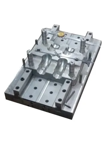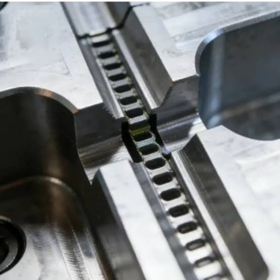
1. Introduction to Venting in Injection Moulds
Venting in injection moulds is the process of allowing trapped air, gases, and volatile substances to escape from the mould cavity during the injection moulding process. It is an important part of mould design because air trapped inside the cavity can prevent molten plastic from filling the mould properly and can cause defects in the finished component.
In injection moulding, molten plastic is injected under pressure into a closed mould cavity. As the plastic flows through the cavity, it displaces the air already present. If the displaced air cannot escape, it becomes compressed and may create problems such as burn marks, incomplete filling, poor surface finish, and dimensional defects.
A properly designed venting system provides controlled escape paths for air and gases while preventing excessive molten plastic from leaking out of the cavity.
2. Importance of Venting in Injection Moulds
Venting is essential for achieving consistent product quality and efficient production.
The main purposes of venting are:
- Removal of trapped air: Allows air inside the cavity to escape as the plastic enters.
- Prevention of burn marks: Reduces the risk of compressed air and gas heating enough to burn or degrade the plastic.
- Improved cavity filling: Helps molten plastic reach the extremities of the mould cavity.
- Reduction of short shots: Minimises incomplete filling caused by trapped air or gas.
- Improved surface finish: Helps prevent bubbles, gas-related blemishes, and other surface defects.
- Reduced moulding pressure requirements: Effective venting may reduce resistance to filling in suitable applications.
- Improved production consistency: Helps reduce rejects and interruptions caused by moulding defects.
- Protection of mould components: Reduces the risk of excessive gas pressure and associated damage in poorly vented areas.
3. Working Principle of Venting
The venting process operates alongside the flow of molten plastic.
- The mould closes, forming the cavity into which the plastic will be injected.
- Molten plastic enters the cavity through the sprue, runner, and gate.
- The advancing plastic front pushes the air ahead of it.
- Air and gases escape through vents, parting-line clearances, ejector clearances, or dedicated vent channels.
- The plastic continues filling the cavity while the displaced gases leave the mould.
- The cavity becomes filled, and the plastic cools and solidifies.
Vents must be designed with suitable dimensions. If a vent is too shallow or blocked, air may remain trapped. If it is too deep, molten plastic may enter the vent and form excessive flash.
The correct vent dimensions depend on the plastic material, its viscosity, moulding conditions, mould construction, and the location of the vent.
4. Types of Venting in Injection Moulds
A. Parting-Line Venting
Parting-line venting is one of the most common venting methods. It uses carefully controlled shallow channels at the interface between the two mould halves.
When the mould closes, the parting-line vents provide a path for air to escape without allowing excessive plastic leakage.
Advantages:
- Simple and economical to manufacture.
- Easy to inspect and clean.
- Can be incorporated into the existing mould parting line.
- Suitable for many conventional mould designs.
Applications: Plastic housings, covers, containers, caps, and general-purpose injection-moulded components.
Limitation: The effectiveness of parting-line vents depends on their location and dimensions. Incorrect design may cause flash or inadequate gas removal.
B. Ejector-Pin Venting
Ejector-pin venting uses the small clearance between an ejector pin and its surrounding bore to allow trapped air to escape.
Ejector pins are normally intended to remove the finished part from the mould. In suitable designs, their clearances can also provide an additional venting path.
Advantages:
- Uses existing mould components.
- Can help release air from specific areas of the cavity.
- May reduce the need for separate vent channels in selected locations.
Applications: Parts with ribs, bosses, deep cavities, and localised areas where air tends to accumulate.
Limitation: Ejector-pin clearances must be controlled carefully. Excessive clearance may cause flash, while insufficient clearance or contamination may prevent effective venting.
C. Vent Grooves or Vent Channels
Vent grooves are specially machined shallow channels that carry air away from the cavity toward the outside of the mould.
These channels are positioned where the advancing plastic front is likely to trap air or where gases need a defined escape route.
Advantages:
- Allows venting at selected locations.
- Can be designed for difficult cavity geometries.
- Provides a controlled path for air and gases.
- Can improve filling in areas that are prone to air entrapment.
Applications: Complex components, large mould cavities, ribbed parts, and moulds with multiple flow fronts.
Limitation: Vent channels require suitable dimensions and regular cleaning. Poorly designed channels may cause flash or fail to remove gases efficiently.
D. Porous-Metal Venting
Porous-metal venting uses a specially manufactured porous insert through which gas can pass while molten plastic is largely prevented from penetrating the insert under the intended processing conditions.
The insert is installed in a location where trapped air is likely to accumulate.
Advantages:
- Can provide distributed venting over a selected area.
- Useful for complex geometries.
- May improve gas removal where conventional vent channels are difficult to incorporate.
Applications: Deep cavities, complex moulded parts, and specialised tooling requiring localised or distributed venting.
Limitation: Porous inserts can become clogged with plastic residue or contaminants. They may also require specialised cleaning and maintenance.
E. Vacuum Venting
Vacuum venting uses a vacuum system to remove air from the mould cavity before or during the injection process, depending on the system design.
The vacuum reduces the amount of air initially present, helping the molten plastic fill difficult areas.
Advantages:
- Can improve filling in complex cavities.
- Helps reduce gas-related defects.
- Useful for components with thin sections or intricate details.
- Can support more consistent mould filling under suitable conditions.
Applications: Precision moulding, thin-walled components, complex engineering parts, and selected large or technically demanding mouldings.
Limitation: Vacuum venting requires additional equipment, seals, passages, and control systems. The system must be maintained to prevent leakage and loss of vacuum performance.
F. Insert Venting
Insert venting uses removable or specially designed mould inserts to provide venting at particular locations.
The inserts may be positioned at cavity ends, deep recesses, or other regions where trapped gases are likely to collect.
Advantages:
- Allows venting to be added to selected areas.
- Can simplify maintenance when inserts are removable.
- Offers flexibility for complex mould designs.
Applications: Deep cavities, specialised components, and moulds requiring venting in areas that are difficult to machine directly.
Limitation: Insert alignment, sealing, and vent dimensions must be maintained to prevent leakage, flash, and inconsistent venting.
5. Comparison of Venting Methods
| Venting method | Main principle | Typical application |
|---|---|---|
| Parting-line venting | Air escapes through shallow channels at the mould split | General plastic components |
| Ejector-pin venting | Air escapes through controlled pin clearances | Ribs, bosses, localised trapped-air areas |
| Vent grooves | Air travels through dedicated channels | Complex cavity geometries |
| Porous-metal venting | Gas passes through a porous insert | Difficult-to-vent cavity areas |
| Vacuum venting | Air is removed using a vacuum system | Precision and complex mouldings |
| Insert venting | Special inserts provide escape paths | Deep or specialised cavities |
6. Location of Vents in Injection Moulds
Correct vent placement is just as important as vent size. Vents should be positioned where air is most likely to become trapped as molten plastic fills the cavity.
Common vent locations include:
- End-of-fill regions: Areas reached by the advancing plastic front near the end of filling.
- Weld-line regions: Areas where separate flow fronts meet, which may trap gas or air.
- Deep ribs and bosses: Features that can restrict the escape of air.
- Corners and recesses: Areas where the flow pattern may leave isolated pockets of air.
- Areas opposite the gate: Locations where the plastic front may push air toward the far end of the cavity.
- Near ejector pins or inserts: Suitable locations where clearances or designed passages can provide venting.
Vents should be located according to the actual flow pattern, not simply distributed uniformly around the mould. Flow simulation, mould trials, and inspection of moulding defects can help determine where additional vents are needed.
7. Factors Affecting Venting Performance
1. Vent Depth
Vent depth is the height of the shallow channel through which gas escapes. It must be selected according to the material and processing conditions.
A vent that is too shallow may restrict air flow. A vent that is too deep may allow plastic to enter the channel, creating flash.
2. Vent Width
Vent width affects the amount of air that can pass through the vent. Wider channels can increase gas flow capacity, but the required width depends on the cavity geometry and vent arrangement.
3. Vent Length
The length of the vent path affects flow resistance. Excessively long or restrictive vent paths can reduce venting effectiveness.
4. Plastic Material
Different polymers have different viscosities, flow characteristics, and gas-generation behaviour. Materials that generate more volatile substances during processing may require additional attention to venting.
5. Injection Speed
High injection speeds can cause the plastic front to reach the end of the cavity quickly, compressing air before it has time to escape. Optimised injection speed can improve filling and reduce trapped-gas defects.
6. Mould Temperature
Mould temperature affects the viscosity and solidification behaviour of the plastic. It also influences the way the flow front advances through the cavity.
7. Mould Cleanliness
Plastic residue, oil, dust, and deposits can block vents. Regular cleaning is essential to maintain consistent airflow.
8. Common Problems Caused by Poor Venting
A. Burn Marks
Burn marks are dark or discoloured areas on the moulded component. They may occur when trapped air or gas becomes highly compressed and heats up, damaging the polymer.
Prevention: Improve venting at the affected location, inspect for blocked vents, and optimise injection speed and processing conditions.
B. Short Shots
A short shot occurs when the plastic does not completely fill the mould cavity. Trapped air can resist the advancing plastic front and contribute to incomplete filling.
Prevention: Check vent locations, clear blocked channels, and verify material temperature, injection pressure, and flow conditions.
C. Flash
Flash is a thin layer of excess plastic that escapes through the parting line or another clearance.
Prevention: Inspect vent dimensions, verify mould clamping and alignment, and ensure that processing pressure is appropriate.
D. Weld-Line Defects
A weld line forms where two plastic flow fronts meet. Poor venting in this area may contribute to weak bonding or visible surface defects.
Prevention: Improve venting near the meeting point of the flow fronts and review gate placement and filling conditions.
E. Surface Imperfections
Trapped gases may cause bubbles, blemishes, rough patches, or other surface defects.
Prevention: Clean the mould, ensure suitable venting, and review material drying and processing conditions where relevant.
9. Maintenance of Venting Systems
Regular maintenance ensures that vents continue to function correctly.
Important maintenance practices include:
- Inspect vents regularly for blockage, wear, or damage.
- Clean vent grooves using methods compatible with the mould material.
- Avoid enlarging vent channels unintentionally during cleaning.
- Check ejector-pin clearances and movement.
- Inspect porous inserts for contamination.
- Verify vacuum lines, seals, and connections in vacuum-assisted systems.
- Record recurring defects and identify whether they are linked to specific vent locations.
- Recheck vent dimensions after mould repairs or modifications.
Maintenance intervals should be based on the polymer being processed, production volume, and the tendency of the material to leave deposits.
10. Best Practices for Designing an Effective Venting System
- Identify the likely air-trap locations during mould design.
- Place vents near end-of-fill areas and other gas-accumulation points.
- Select vent dimensions appropriate for the polymer and processing conditions.
- Use multiple venting methods where a single method is insufficient.
- Ensure vent channels lead to an effective escape path.
- Avoid vent designs that create excessive flash.
- Consider flow simulation for complex mould cavities.
- Validate vent performance through mould trials and part inspection.
- Keep venting features accessible for routine maintenance.
Conclusion
Venting in injection moulds is essential for removing trapped air and gases during the filling process. Effective venting helps prevent burn marks, short shots, surface defects, and other moulding problems while improving production consistency.
The main venting methods include parting-line venting, ejector-pin venting, vent grooves, porous-metal inserts, vacuum venting, and insert venting. Each method offers different benefits and is selected according to the mould design, plastic material, component geometry, and production requirements.
A well-designed and properly maintained venting system improves mould filling, reduces rejected components, and supports efficient, high-quality injection moulding.