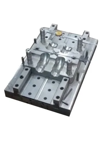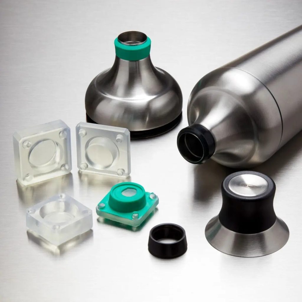
Compression mould design involves designing a mould that can safely and efficiently shape a material under heat and pressure. Compression moulding is commonly used for thermosetting plastics, rubber, silicone, composite materials, and certain thermoplastics.
A good mould design should provide accurate dimensions, uniform material flow, effective heating, easy part removal, and consistent production.
1. Basic Parts of a Compression Mould
A typical compression mould consists of several important components:
| Component | Function |
|---|---|
| Upper Mould | Applies pressure to the material |
| Lower Mould | Contains or supports the cavity |
| Cavity | Creates the external shape of the part |
| Core | Creates internal features or holes |
| Guide Pins | Maintain alignment |
| Bushes | Guide the pins accurately |
| Heating System | Provides the required mould temperature |
| Ejector System | Helps remove the finished part |
| Vents | Allow trapped air and gases to escape |
| Flash Land | Controls excess material at the parting line |
2. Parting Line
The parting line is the surface where the mould sections separate.
A properly positioned parting line should:
- Allow easy removal of the component.
- Minimize visible mould marks where required.
- Simplify mould construction.
- Reduce excessive flash.
- Provide suitable access for trimming.
The parting line should generally follow a location that makes demoulding as straightforward as possible.
3. Cavity and Core Design
The cavity creates the outside shape of the component, while the core forms internal features.
Important considerations include:
- Required product dimensions
- Material shrinkage
- Wall thickness
- Internal holes and openings
- Surface finish
- Ease of demoulding
Sharp internal corners should generally be avoided where possible because suitable radii can improve material flow and reduce stress concentration.
4. Draft Angle
A draft angle is a slight taper provided on mould surfaces to make part removal easier.
Without sufficient draft, the finished component may stick to the mould.
Draft requirements depend on:
- Material
- Surface finish
- Part geometry
- Mould material
- Demoulding method
Textured surfaces generally require more draft than smooth surfaces.
5. Shrinkage Allowance
Many moulding materials shrink as they cool or cure.
Therefore, the mould dimensions may need to be adjusted to compensate for the expected material shrinkage.
The required allowance depends on:
- Material type
- Material formulation
- Cure conditions
- Part geometry
- Fibre or filler content
Accurate shrinkage data from the material supplier is useful during mould design.
6. Flash and Flash Land
During compression moulding, excess material can escape from the moulding area and form flash along the parting line.
A flash land is designed to control this excess material.
Good flash-land design helps:
- Control flash thickness
- Improve mould sealing
- Reduce material waste
- Simplify trimming
7. Venting
Air and gases can become trapped inside the mould cavity.
Proper venting provides a path for these gases to escape.
Poor venting can result in:
- Air traps
- Burn marks
- Incomplete filling
- Surface defects
- Voids
- Inconsistent product quality
Vent locations should be selected based on the material flow and cavity geometry.
8. Heating System
Many compression moulding processes require the mould to operate at an elevated temperature.
Heating can be provided through:
- Electrical heaters
- Cartridge heaters
- Heating plates
- Oil circulation
- Steam systems
The heating system should provide uniform temperature distribution across the mould.
Uneven heating can cause differences in curing, shrinkage, dimensions, and surface quality.
9. Cooling System
Some moulds require controlled cooling after forming or curing.
Cooling channels can help:
- Reduce cycle time
- Control mould temperature
- Improve dimensional stability
- Prevent excessive heat accumulation
The cooling system should be designed so that temperature remains reasonably uniform throughout the mould.
10. Ejection System
The finished component must be removed without damage.
Possible ejection methods include:
- Ejector pins
- Ejector plates
- Stripper plates
- Air ejection
- Manual removal
Ejectors should be positioned carefully to avoid leaving unwanted marks or deforming thin sections.
11. Guide and Alignment System
Accurate alignment between mould halves is essential.
Common components include:
- Guide pins
- Guide bushes
- Alignment blocks
- Locating features
Proper alignment helps prevent:
- Uneven flash
- Core damage
- Cavity mismatch
- Dimensional errors
- Premature mould wear
12. Material Flow Considerations
The mould should allow the material to distribute effectively throughout the cavity.
Designers should consider:
- Charge placement
- Material quantity
- Cavity geometry
- Pressure
- Temperature
- Flow distance
Poor material flow can cause incomplete filling, air entrapment, or uneven properties.
13. Surface Finish
The mould surface determines much of the final surface appearance of the component.
Different finishes can be used depending on the product:
- Polished
- Matte
- Textured
- Patterned
The required finish should be specified during mould design and manufacturing.
14. Mould Material Selection
Common materials include:
- Tool steels
- Alloy steels
- Stainless steels
- Aluminum for certain applications
- Specialized tooling materials
Material selection depends on:
- Moulding temperature
- Pressure
- Production volume
- Abrasion
- Corrosion
- Required surface finish
- Expected mould life
Basic Compression Mould Design Process
A typical design sequence is:
1. Define the product requirements
Determine dimensions, tolerances, material, surface finish, and production quantity.
2. Analyze the component geometry
Identify cores, cavities, holes, undercuts, wall thickness, and draft requirements.
3. Select the parting line
Choose a suitable separation plane for easy moulding and demoulding.
4. Design the cavity and core
Create the mould surfaces while accounting for material shrinkage.
5. Design vents and flash lands
Provide suitable paths for air and control excess material.
6. Design heating and cooling
Position heating or cooling elements for relatively uniform temperature control.
7. Design the ejection system
Select an appropriate method for removing the finished part.
8. Add alignment features
Use guide pins, bushes, and locating features.
9. Check mould strength
Ensure the mould can withstand the required compression pressure and operating temperature.
10. Manufacture and test the mould
Conduct trial moulding and make necessary adjustments.
Common Compression Mould Designs
Some common configurations include:
Positive Mould: The material is compressed between a punch and cavity with relatively close control of the moulding area.
Semi-Positive Mould: Provides a balance between positive and flash-type moulding approaches.
Flash Mould: Allows excess material to escape around the parting area, creating flash that is trimmed after moulding.
Common Design Problems
Poor mould design can result in:
- Excessive flash
- Incomplete filling
- Air entrapment
- Uneven curing
- Part sticking
- Dimensional variation
- Surface defects
- Mould wear
- Difficult demoulding
These issues can often be reduced through proper parting-line selection, draft, venting, material-flow planning, temperature control, and ejection design.
In Short
Compression mould design basics focus on creating a mould that can withstand heat and pressure while providing controlled material flow, accurate dimensions, efficient curing, proper venting, and easy part removal.
The most important design elements are the cavity, core, parting line, draft angle, shrinkage allowance, flash land, vents, heating/cooling system, alignment system, and ejection system. A well-designed mould improves product quality, reduces defects, and increases mould life.