1. Introduction
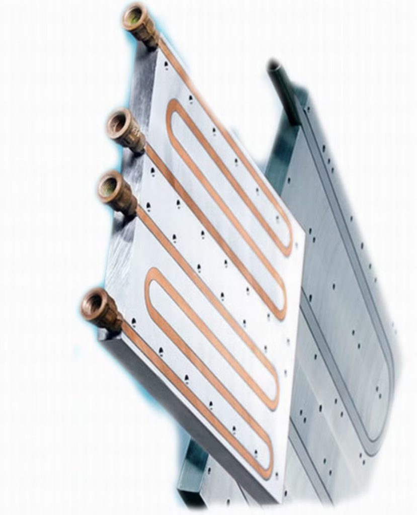
Cooling channel design is the process of designing passages or pathways through which a cooling fluid, such as water, oil, air, or another coolant, flows to remove heat from a component or system.
Cooling channels are widely used in injection molding, die casting, CNC machining, internal combustion engines, electronic devices, heat exchangers, and industrial equipment. Their main purpose is to maintain a suitable operating temperature, improve thermal efficiency, and prevent overheating.
In manufacturing, particularly in plastic injection molding, cooling channel design is extremely important because cooling often accounts for a substantial portion of the total production cycle. An efficient channel layout can reduce cycle time, improve product quality, and increase manufacturing productivity.
2. Objectives of Cooling Channel Design
The main objectives of cooling channel design include:
- Efficient heat removal: Remove heat from hot components as quickly and uniformly as practical.
- Temperature uniformity: Minimize temperature differences across the surface or volume of the component.
- Reduced cycle time: Shorten cooling periods in manufacturing processes.
- Improved product quality: Reduce warpage, shrinkage variation, residual stresses, and dimensional inaccuracies.
- Energy efficiency: Reduce the energy required to circulate the coolant and operate associated equipment.
- Reliable operation: Avoid excessive pressure drops, leakage, blockage, and local overheating.
- Longer equipment life: Reduce thermal stresses and temperature-related degradation.
The appropriate design depends on the application, heat load, available space, coolant properties, operating pressure, and manufacturing method.
3. Main Components of a Cooling Channel System
A typical cooling channel system consists of several elements.
A. Cooling Channels
These are the internal passages through which the coolant flows. They may be straight, curved, branched, or arranged in a complex network.
Channel diameter, cross-sectional shape, spacing, and length determine the flow resistance and heat-transfer performance.
B. Coolant
The coolant absorbs heat from the surrounding material and carries it away.
Common coolants include:
- Water
- Water-glycol mixtures
- Thermal oils
- Air
- Specialized industrial heat-transfer fluids
Water is widely used because it has a relatively high specific heat capacity and good heat-transfer properties. The coolant must also be compatible with the channel material and operating conditions.
C. Inlet and Outlet Ports
The inlet introduces relatively cool fluid into the channel system, while the outlet carries heated fluid away.
Their locations affect the flow distribution, pressure loss, accessibility, and temperature uniformity.
D. Pump or Circulation System
A pump provides the pressure needed to move the coolant through the channels. Its capacity must be sufficient to overcome pressure losses in the channels, fittings, manifolds, and other components.
E. Heat-Transfer Surface
This is the solid material separating the coolant from the hot component. Heat passes through the solid by conduction and transfers to the coolant by convection.
The thickness and thermal conductivity of this material influence how effectively heat reaches the coolant.
F. Manifolds and Connectors
Manifolds distribute coolant among multiple channels and collect it after circulation. Their geometry affects flow balance, pressure loss, and the likelihood of stagnant regions.
4. Types of Cooling Channel Designs
4.1 Straight Cooling Channels
Straight channels are simple passages arranged parallel or perpendicular to a component’s main surfaces.
Advantages:
- Easy to manufacture
- Simple to clean and inspect
- Relatively low production cost
- Predictable flow behavior
Limitations:
- May not follow complex component geometry
- Can produce uneven cooling in regions far from the channels
- May require additional channels to cover complex surfaces
Straight channels are commonly used in conventional molds, engine components, and simple heat exchangers.
4.2 Conformal Cooling Channels
Conformal cooling channels follow the contours of a component or mold cavity. They are particularly important in additive manufacturing, where complex internal passages can be produced.
Unlike straight channels, conformal channels can maintain a more consistent distance from curved or irregular surfaces.
Advantages:
- More uniform temperature distribution
- Potentially shorter cooling cycles
- Reduced thermal gradients
- Improved dimensional stability
- Better cooling of complex geometries
Limitations:
- More complex design and manufacturing
- Higher initial production cost
- Difficult inspection and cleaning
- Possible pressure loss in curved or complex passages
- Greater dependence on manufacturing quality
Conformal channels are often used in high-performance injection molds and additively manufactured tooling.
4.3 Spiral Cooling Channels
Spiral channels follow a helical or spiral-shaped path. They can be used when heat must be removed from cylindrical or approximately cylindrical components.
Advantages:
- Good coverage of curved surfaces
- Compact arrangement
- Potentially improved circumferential temperature uniformity
Limitations:
- Curved paths may increase flow resistance
- The flow distribution depends on channel geometry
- Manufacturing and cleaning may be more difficult than for straight passages
4.4 Parallel Cooling Channels
Parallel channels divide the coolant among multiple branches.
Advantages:
- Can provide broad cooling coverage
- May reduce the flow length through each branch
- Can support high overall heat-transfer capacity
Limitations:
- Unequal hydraulic resistance may cause flow maldistribution
- Some branches may receive less coolant than others
- Requires careful manifold and channel sizing
Parallel systems should be designed to distribute coolant evenly across all branches.
4.5 Series Cooling Channels
In a series arrangement, coolant passes through one channel and then continues through subsequent channels.
Advantages:
- Simple flow path
- Easier control of flow sequence
- Fewer distribution branches
Limitations:
- Coolant temperature rises along the flow path
- Downstream regions may receive warmer coolant
- Pressure drop accumulates along the circuit
Series channels may be suitable for applications where the heat load is relatively uniform and the total channel length is manageable.
4.6 Bubbler and Baffle Cooling
These techniques are commonly used in injection molding to cool deep or narrow regions.
- Bubblers: A tube delivers coolant to a deep region, and the fluid returns through the surrounding passage.
- Baffles: A plate divides a cooling passage, directing coolant toward specific areas before it returns.
Both methods can improve cooling in regions that are difficult to reach with conventional straight channels.
5. Important Parameters in Cooling Channel Design
The effectiveness of a cooling channel depends on several interacting parameters.
| Parameter | Description | Effect on performance |
|---|---|---|
| Channel diameter | Internal width of a circular channel | Influences flow rate, pressure loss, and heat transfer |
| Channel spacing | Distance between adjacent channels | Affects temperature uniformity and cooling coverage |
| Distance from the surface | Thickness of material between the channel and hot surface | Influences heat conduction and structural strength |
| Channel length | Total distance traveled by the coolant | Affects pressure drop and coolant temperature rise |
| Coolant flow rate | Volume or mass of coolant passing through the system | Influences heat removal and temperature distribution |
| Coolant temperature | Temperature at the inlet and throughout the channel | Determines the available temperature difference for heat transfer |
| Surface roughness | Texture of the internal channel surface | Affects friction and may influence heat transfer |
| Channel shape | Circular, rectangular, curved, or other geometry | Influences hydraulic resistance and manufacturability |
| Channel material | Material surrounding the coolant passage | Determines thermal conductivity, strength, and corrosion resistance |
These parameters should be optimized together rather than selected independently.
6. Heat Transfer Principles
Cooling channel design is based on three fundamental heat-transfer mechanisms.
A. Conduction
Conduction transfers heat through the solid material separating the hot surface from the cooling channel.
For one-dimensional steady conduction through a flat wall:
\[ Q = \frac{kA(T_h-T_c)}{L} \]
Where:
- \(Q\) = heat-transfer rate in watts
- \(k\) = thermal conductivity of the solid in W/(m·K)
- \(A\) = heat-transfer area in m²
- \(T_h\) = hot-side temperature
- \(T_c\) = cold-side temperature
- \(L\) = wall thickness in meters
A thinner wall or a material with higher thermal conductivity generally reduces conduction resistance, although the wall must remain strong enough for the operating pressure and mechanical loads.
B. Convection
Convection transfers heat from the channel wall to the flowing coolant.
Newton’s law of cooling is:
\[ Q = hA(T_w-T_f) \]
Where:
- \(h\) = convective heat-transfer coefficient in W/(m²·K)
- \(A\) = heat-transfer area
- \(T_w\) = channel wall temperature
- \(T_f\) = representative coolant temperature
The heat-transfer coefficient depends on coolant properties, velocity, channel geometry, and flow regime.
C. Fluid Heat Absorption
The coolant absorbs energy as it passes through the channel.
For a coolant with approximately constant specific heat:
\[ Q = \dot{m}c_p(T_{\text{out}}-T_{\text{in}}) \]
Where:
- \(\dot{m}\) = coolant mass flow rate in kg/s
- \(c_p\) = specific heat capacity in J/(kg·K)
- \(T_{\text{in}}\) = inlet temperature
- \(T_{\text{out}}\) = outlet temperature
This equation helps estimate the coolant flow required to remove a specified heat load.
7. Fluid Flow Considerations
Cooling channels must provide adequate coolant circulation without excessive pumping requirements.
Reynolds Number
The Reynolds number indicates whether the flow is generally laminar or turbulent in a given internal-flow configuration.
\[ Re = \frac{\rho vD_h}{\mu} \]
Where:
- \(\rho\) = coolant density in kg/m³
- \(v\) = average flow velocity in m/s
- \(D_h\) = hydraulic diameter in meters
- \(\mu\) = dynamic viscosity in Pa·s
For a circular channel, the hydraulic diameter is equal to the internal diameter.
In a conventional circular pipe, flow is generally laminar below a Reynolds number of approximately 2,300, transitional over an intermediate range, and turbulent above approximately 4,000. These thresholds are approximate and depend on the flow conditions.
Turbulent flow often improves convective heat transfer, but it also generally increases pressure loss.
Pressure Drop
The pressure drop along a straight channel can be estimated using the Darcy–Weisbach equation:
\[ \Delta P = f\frac{L}{D_h}\frac{\rho v^2}{2} \]
Where:
- \(\Delta P\) = pressure drop in pascals
- \(f\) = Darcy friction factor
- \(L\) = channel length
- \(D_h\) = hydraulic diameter
- \(\rho\) = coolant density
- \(v\) = average velocity
Additional losses occur at bends, entrances, exits, valves, and manifolds.
The pump must provide sufficient pressure to overcome the total system resistance at the required flow rate.
8. Design Procedure for Cooling Channels
A systematic design process improves thermal performance and reliability.
Step 1: Define the application.
Identify the component to be cooled, the operating conditions, the heat load, the allowable temperature range, and any dimensional constraints.
Step 2: Determine the heat load.
Estimate the amount of heat that must be removed and the time available for cooling. Consider transient heating if the system operates in repeated cycles.
Step 3: Select the coolant.
Choose a fluid based on thermal properties, operating temperature, corrosion compatibility, viscosity, safety, and environmental requirements.
Step 4: Choose the channel arrangement.
Determine whether straight, conformal, spiral, parallel, series, or specialized channels are most appropriate.
Step 5: Select preliminary dimensions.
Estimate channel diameter, spacing, wall thickness, channel length, and distance from the cooled surface.
Step 6: Calculate flow requirements.
Use heat-balance equations to estimate the necessary mass flow rate. Check the Reynolds number and expected pressure drop.
Step 7: Analyze thermal performance.
Evaluate temperature distribution, heat-transfer rates, and local hot spots using analytical calculations or computational fluid dynamics (CFD).
Step 8: Check mechanical integrity.
Verify that the channel walls and surrounding structure can withstand operating pressure, thermal expansion, mechanical loads, and repeated temperature cycles.
Step 9: Manufacture and inspect.
Produce the channels using an appropriate process, such as drilling, milling, casting, brazing, or additive manufacturing. Inspect for dimensional accuracy, blockages, leaks, and surface defects.
Step 10: Test and optimize.
Measure inlet and outlet temperatures, coolant flow, pressure drop, and component temperature. Compare actual performance with design predictions and adjust the design if necessary.
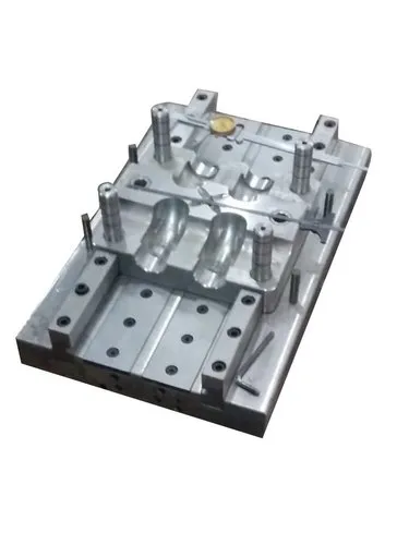
9. Cooling Channel Design in Injection Molding
Injection molding is one of the most important applications of cooling channel design.
During injection molding, molten plastic enters a mold cavity and transfers heat to the mold. The plastic must cool sufficiently before the molded component can be ejected without unacceptable deformation.
Cooling channels are typically incorporated into the mold core and cavity to remove heat from the plastic.
Key design considerations
- Uniform channel spacing: Helps maintain consistent cooling across the molded part.
- Appropriate surface distance: Channels should be close enough to remove heat efficiently but far enough away to preserve mold strength.
- Balanced coolant distribution: Reduces differences in temperature between mold regions.
- Cooling of thick sections: Thick regions often cool more slowly and may require special attention.
- Conformal cooling: Can follow complex cavity shapes more closely than conventional drilled channels.
- Cycle-time optimization: Effective cooling can reduce the time required before ejection.
Uneven cooling may cause warpage, sink marks, residual stresses, dimensional variation, and differences in surface finish.
Conformal cooling can improve temperature uniformity in suitable applications, but its performance depends on channel geometry, manufacturing accuracy, coolant flow, and the thermal properties of the mold material.
10. Common Cooling Channel Design Problems
| Problem | Possible cause | Potential solution |
|---|---|---|
| Uneven cooling | Poor channel placement or flow distribution | Optimize spacing and balance the branches |
| Excessive pressure drop | Channels are too narrow or long | Increase hydraulic diameter or shorten the flow path |
| Local hot spots | Inadequate cooling coverage | Add or reposition channels |
| Leakage | Defective joints, cracks, or poor manufacturing | Improve sealing and perform pressure testing |
| Channel blockage | Debris, corrosion, or deposits | Improve filtration and maintenance |
| Excessive pumping energy | High hydraulic resistance | Reduce pressure losses and optimize flow |
| Warpage in molded parts | Uneven temperature distribution or shrinkage | Improve thermal uniformity and validate the molding process |
| Corrosion | Incompatible coolant and channel material | Select compatible materials and coolant treatment |
11. Software Used for Cooling Channel Design
Computer-aided engineering tools can help engineers evaluate complex cooling systems before manufacturing.
Common software categories include:
- CAD software: Used to create channel geometry and integrate channels into components.
- CFD software: Used to simulate coolant flow, pressure distribution, and convective heat transfer.
- Thermal simulation software: Used to predict temperature distributions and transient cooling behavior.
- Injection molding simulation software: Used to evaluate mold cooling, cycle time, and molded-part quality.
- Finite element analysis (FEA) software: Used to assess thermal stresses, structural deformation, and pressure-related loads.
Examples of software packages include ANSYS Fluent, COMSOL Multiphysics, Autodesk Moldflow, and SOLIDWORKS Simulation. The appropriate tool depends on the application and the required level of analysis.
12. Modern Trends in Cooling Channel Design
Modern cooling channel development focuses on improving heat transfer while reducing energy use and manufacturing costs.
Important trends include:
- Conformal cooling: Channels follow complex component contours to improve thermal uniformity.
- Additive manufacturing: Enables internal channel shapes that are difficult or impossible to produce using conventional drilling.
- Topology optimization: Helps identify efficient channel layouts within geometric and structural constraints.
- CFD-based optimization: Allows engineers to compare alternative designs before manufacturing.
- Advanced materials: High-conductivity materials and corrosion-resistant alloys can improve performance in suitable applications.
- Smart monitoring: Temperature, pressure, and flow sensors can help detect blockages, leakage, or abnormal operating conditions.
- Energy-efficient circulation: Pump and flow-control optimization can reduce operating costs while maintaining adequate cooling.
Conclusion
Cooling channel design is a critical engineering activity involving the coordinated selection of channel geometry, coolant properties, flow rate, heat-transfer surfaces, and manufacturing methods. A successful design must remove heat efficiently, maintain temperature uniformity, control pressure losses, and preserve mechanical strength.
In applications such as injection molding, effective cooling channel design can improve product quality, reduce cycle time, and increase production efficiency. In all applications, the best design is the one that meets thermal and structural requirements while remaining practical to manufacture, inspect, maintain, and operate.