An injection mould is a complex tool used in the injection moulding process to shape plastic into desired forms. It consists of several precisely engineered components that work together to produce accurate and consistent parts. The mould is typically divided into two main halves: the core side (moving half) and the cavity side (stationary half).
Below are the main components of an injection mould:
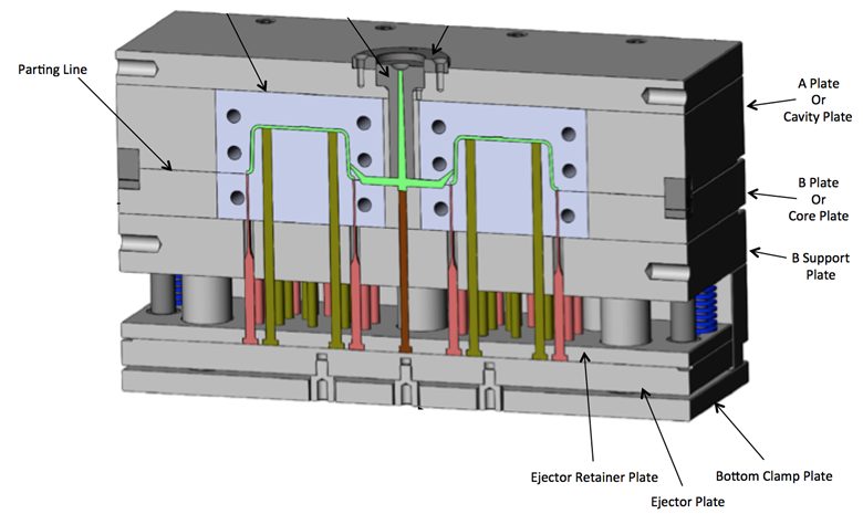
1. Cavity Plate
Also known as the female part of the mould.
Forms the external shape of the plastic part.
Fixed to the stationary platen of the injection moulding machine.
2. Core Plate
Also known as the male part of the mould.
Forms the internal shape of the part.
Attached to the moving platen of the machine.
Enters the cavity during mould closing to form the part shape.
3. Sprue
The channel through which molten plastic enters the mould from the injection nozzle.
Located at the centre of the mould.
Leads to the runner system.
4. Runner
A system of channels that distribute the molten plastic from the sprue to multiple cavities (in multi-cavity moulds).
Can be cold runners (material solidifies) or hot runners (kept heated to avoid solidification).
5. Gate
The small opening that connects the runner to the mould cavity.
Controls the flow of plastic into the cavity.
Types include edge gate, pin gate, submarine gate, etc.
6. Ejector System
Removes the finished part from the mould.
Consists of:
Ejector pins
Ejector plate
Return pins
Mounted on the core side (moving half).
Activated after mould opens.
7. Cooling System
Circulates coolant (usually water) to regulate mould temperature.
Maintains consistent processing temperature and reduces cycle time.
Includes cooling channels drilled into mould plates.
8. Venting System
Allows trapped air and gases to escape from the cavity as plastic fills it.
Usually consists of small grooves around the cavity or parting line.
Essential for avoiding burn marks and incomplete filling.
9. Clamping/Support Plates
Provide support and alignment for other mould components.
Includes:
Top clamping plate (attaches mould to machine platen)
Bottom clamping plate
Back plates (for additional support and stability)
10. Guide Pins and Bushings
Ensure precise alignment of the core and cavity halves during mould closing.
Located at the corners of the mould base.
11. Locating Ring
Helps align the mould with the injection nozzle of the machine.
Mounted on the top clamping plate.
12. Mould Base
The structure that houses all the mould components.
Made up of steel or aluminum plates.
Can be custom-designed or purchased as standard bases.
Optional Components
Depending on the design complexity, additional components may include:
Side cores or sliders (for undercuts)
Hydraulic cylinders (for complex movements)
Unscrewing mechanisms (for threaded parts)
Hot runner systems (for large or multi-cavity moulds)
Conclusion
Understanding the components of an injection mould is essential for designing, operating, and maintaining moulds effectively. Each component plays a crucial role in ensuring the mould functions efficiently and produces high-quality plastic parts with precision and repeatability.