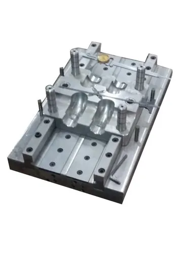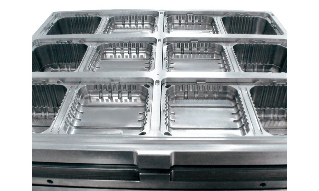
Thermoforming mould design is the process of creating a mould that shapes a heated thermoplastic sheet into a desired product using vacuum, air pressure, or mechanical force. The mould is a critical part of the thermoforming process because its design affects product quality, wall thickness, dimensional accuracy, surface finish, production speed, and material usage.
Thermoforming moulds are widely used in packaging, automotive components, medical trays, appliance housings, and industrial products.
1. What Is Thermoforming Mould Design?
Thermoforming mould design involves developing a mould with the correct shape, dimensions, surface features, and forming characteristics to produce a component from a heated plastic sheet.
The plastic sheet is heated until it becomes flexible, placed over or into the mould, and shaped using vacuum, compressed air, or mechanical assistance. After cooling, the formed product is removed and trimmed.
Basic process:
Plastic Sheet Heating → Sheet Positioning → Forming → Cooling → Demoulding → Trimming
2. Main Components of a Thermoforming Mould
| Component | Function |
|---|---|
| Mould Body | Provides the main structure and product shape |
| Forming Surface | Shapes the heated plastic sheet |
| Male or Female Mould | Determines how the sheet is formed |
| Vacuum Channels | Remove air between the sheet and mould |
| Vent Holes | Allow trapped air to escape |
| Pressure System | Applies compressed air when pressure forming is used |
| Cooling Channels | Help control mould temperature and cooling time |
| Clamping Area | Holds the plastic sheet securely during forming |
| Draft Angles | Help release the formed product |
| Trimming Allowance | Provides material for final cutting |
| Mounting Plate | Secures the mould to the forming machine |
3. Types of Thermoforming Moulds
A. Male or Positive Mould
A male mould has a raised shape over which the heated plastic sheet is formed.
Characteristics:
- The sheet stretches over the mould.
- The mould generally defines the inside surface of the formed product.
- Suitable for some trays, covers, and housings.
B. Female or Negative Mould
A female mould has a cavity into which the heated plastic sheet is drawn.
Characteristics:
- The sheet is formed inside the mould cavity.
- The mould generally defines the outside surface of the product.
- Often used for packaging trays, containers, and shaped covers.
C. Matched Mould
Matched moulds use complementary male and female sections to shape the plastic sheet between them. They can provide greater control over product details and geometry, depending on the process and material.
4. Important Design Elements
A. Part Geometry
The product shape is the starting point of mould design. Designers must consider the depth, width, length, corners, ribs, recesses, and other features of the component.
Complex shapes may require additional forming techniques, such as plug assistance or pressure forming.
B. Draft Angle
Draft is a slight taper applied to vertical or near-vertical mould surfaces. It helps the formed product release from the mould without sticking or damage.
The required draft depends on:
- Product depth
- Surface texture
- Plastic material
- Mould type
- Demoulding method
Deeper parts and textured surfaces often require greater draft.
C. Wall Thickness Distribution
During thermoforming, the heated sheet stretches over the mould. This stretching can cause the material to become thinner, particularly at deep corners and sharply curved areas.
Designers should consider:
- Sheet thickness
- Draw depth
- Corner radius
- Forming temperature
- Plug-assist requirements
- Material distribution
Uniform wall thickness may not always be possible, but the design should avoid excessive thinning in critical areas.
D. Corner Radius
Sharp corners can cause excessive stretching and thinning of the plastic sheet.
Suitable corner radii help:
- Improve material flow
- Reduce stress concentration
- Minimize tearing
- Improve product strength
- Support more consistent forming
E. Vacuum and Venting System
Vacuum forming moulds require channels and small vent holes to remove trapped air between the plastic sheet and the mould surface.
A well-designed vacuum system helps the sheet contact the mould evenly and reproduce the intended details.
Vent holes should be positioned carefully to avoid unwanted marks on visible product surfaces.
F. Cooling System
Cooling channels may be included to remove heat from the formed plastic and maintain consistent mould temperature.
Effective cooling helps:
- Reduce cycle time
- Improve dimensional stability
- Minimize warpage
- Support consistent product quality
G. Surface Finish
The mould surface directly affects the finish of the formed product.
Common finishes include:
- Polished
- Smooth
- Matte
- Textured
- Etched
The required finish depends on the product’s appearance, function, and release requirements.
5. Materials Used for Thermoforming Moulds
| Mould Material | Main Characteristics | Typical Use |
|---|---|---|
| Aluminium | Good heat transfer, machinable, durable | Production moulds |
| Epoxy Tooling | Can reproduce detailed shapes | Prototype and short-run moulds |
| Polyurethane Tooling Board | Easy to machine and modify | Prototype and low-volume production |
| Steel | High strength and wear resistance | Specialized, demanding applications |
| Wood | Low cost and easy to shape | Early prototypes and basic forming trials |
Material selection depends on production volume, mould complexity, forming temperature, required accuracy, and budget.
6. Thermoforming Mould Design Process
Step 1: Define Product Requirements
Determine the product dimensions, shape, wall thickness, material, surface finish, tolerances, and expected production volume.
Step 2: Select the Forming Method
Choose vacuum forming, pressure forming, mechanical forming, or a combined process according to the part geometry and quality requirements.
Step 3: Choose the Mould Type
Select a male, female, or matched mould based on product shape, surface requirements, and forming method.
Step 4: Develop the Mould Geometry
Design the forming surface, draft angles, corner radii, cavity depth, and other product features.
Step 5: Design Vacuum and Venting
Position vacuum channels and vent holes to allow air to escape and support consistent sheet contact.
Step 6: Design Cooling and Mounting
Provide suitable cooling provisions where needed and ensure that the mould can be securely mounted to the thermoforming machine.
Step 7: Manufacture and Test
Produce the mould, conduct forming trials, inspect the parts, and adjust the mould or process settings as necessary.
7. Advantages of Good Thermoforming Mould Design
- Improves product dimensional accuracy.
- Helps achieve more consistent wall thickness.
- Reduces material waste and forming defects.
- Improves surface finish.
- Supports easier demoulding.
- Can reduce production cycle time.
- Improves mould durability and maintainability.
- Helps achieve repeatable production quality.
8. Common Design Problems
| Problem | Possible Cause |
|---|---|
| Excessive thinning | Deep draw, sharp corners, or poor material distribution |
| Webbing | Poor sheet movement or unsuitable mould layout |
| Incomplete forming | Insufficient vacuum, pressure, or forming temperature |
| Warpage | Uneven cooling or residual stresses |
| Sticking | Insufficient draft or unsuitable mould surface |
| Surface marks | Poor vent placement or mould surface defects |
| Uneven wall thickness | Non-uniform stretching or heating |
| Poor dimensional accuracy | Shrinkage, cooling variation, or mould inaccuracies |